Adjustable Engraving Tool Holder

Inactive Publication Date: 2009-12-03
COVER RAYMOND ANTHONY
View PDF21 Cites 12 Cited by
  • Summary
  • Abstract
  • Description
  • Claims
  • Application Information

AI Technical Summary

Benefits of technology

[0015]The present invention is an apparatus and method of fabricating an adjustable engraving tool holder enabling the engraver to adjust the insertion depth of an engraving tool and further providing for easy removal and reinsertion of the engraving tool.
[0030]The invention enables various length engraving tools to be inserted into the engraving tool holder and the overall length of the assembly can be adjusted for consistent length. The adjustable engraving tool holder and engraving tool assembly, provides a tool that is comfortable, has superior tool control characteristics and enhances productivity. The invention further provides an engraving tool holder where the engraving tool is easily removed for sharpening and can be reinserted without the use of additional tools or excessive effort. This facilitates the engraving process by eliminating the need to loosen fasteners, assemble an engraving tool in to a special collet or dismantle the engraving tool holder to remove and sharpen the engraving tool.

Problems solved by technology

Bulino cuts are very repetitive and delicate.
In performing this process, a high frequency of cuts are made per minute and the graver typically requires frequent sharpening.
This tool handle also does not provide for adjusting the length of the graver as it decreases in length.
Thus, an engraver will either have to modify the end of an engraving tool blank, which is time consuming, or purchase an engraving tool blank configured to fit this type of tool handle.
In addition, when this type of tool handle is used in repetitive or high frequency cutting, the sliding tapered sleeve does not adequately secure the graver and the graver will frequently work loose.
The specially configured end will either require additional time to fabricate or require the engraver to incur additional expense by purchasing special blanks.
Furthermore, this style of engraving tool blank, with a specially adapted end, is presently less common as the engraving industry has standardized the use of a blank that is essentially straight and has a square cross-section with no specially configured ends.
Likewise, when this type of tool handle is used in repetitive or high frequency cutting, the sliding sleeve does not retain sufficient tension between the graver, sliding sleeve and handle, and will frequently work loose.
Moreover, this configuration does not provide for an adequate length adjustment, which is necessary as the length of the graver decreases with repetitive sharpening.
Correspondingly, currently available hand-held push engraver handles still suffer from severe deficiencies in providing an adjustable, readily removable and precision graver handle and have not met with significant success to date.

Method used


Image

  • Adjustable Engraving Tool Holder
  • Adjustable Engraving Tool Holder
  • Adjustable Engraving Tool Holder

Examples


Embodiment Construction

[0046]The invention is an adjustable engraving tool holder. In the following description, numerous specific details are set forth in order to provide a more thorough description of the present invention. It will be apparent, however, to one skilled in the art, that the present invention may be practiced without these specific details. In other instances, well-known features have been indicated although not described in detail so as not to obscure the invention.

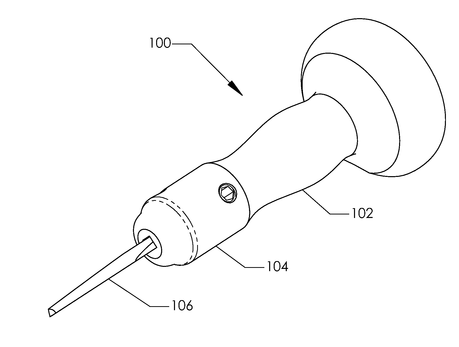
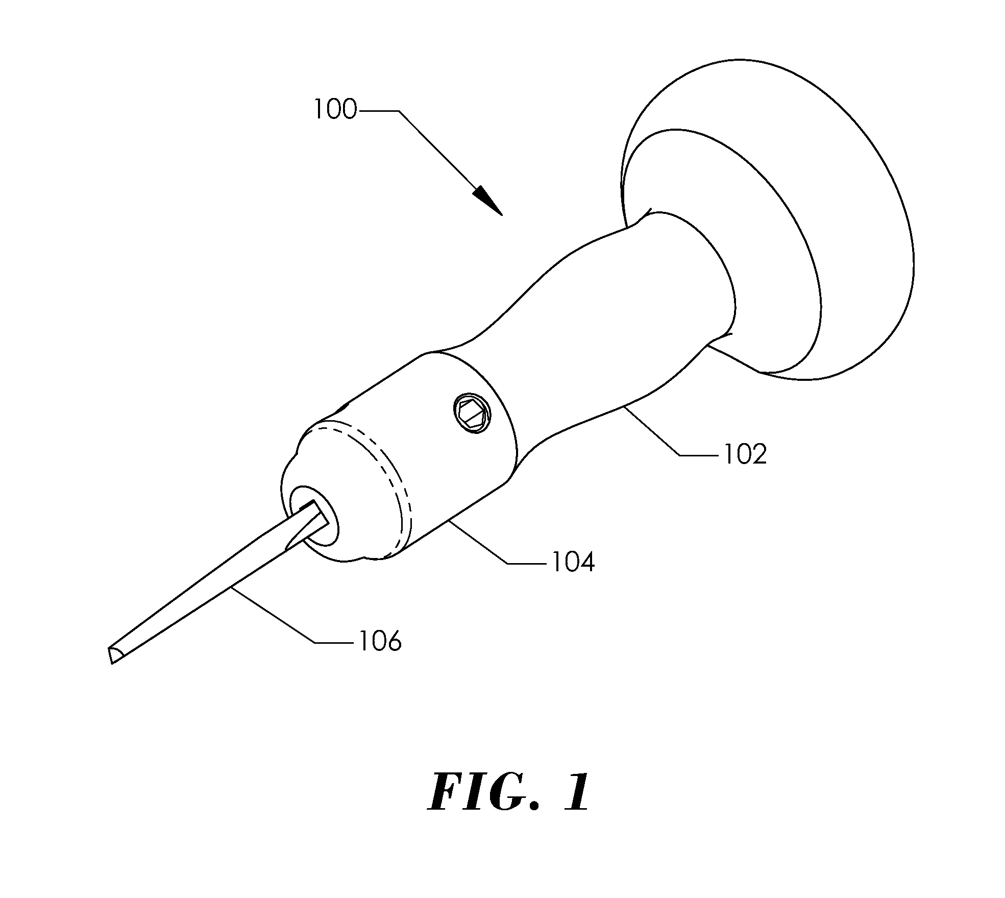
[0047]Referring to the figures, FIG. 1 illustrates an adjustable engraving tool holder 100 having a handle 102 contoured to comfortably fit in the palm of the hand. An engraving tool holder housing 104 is shown with a handle 102 mounted thereon. An engraving tool 106 is inserted into the housing 104. As used herein, the term engraving tool indicates a cutting tool made of tempered steel with a point configured for excising a surface. Such an engraving tool is commonly referred to in the art as a “graver.”

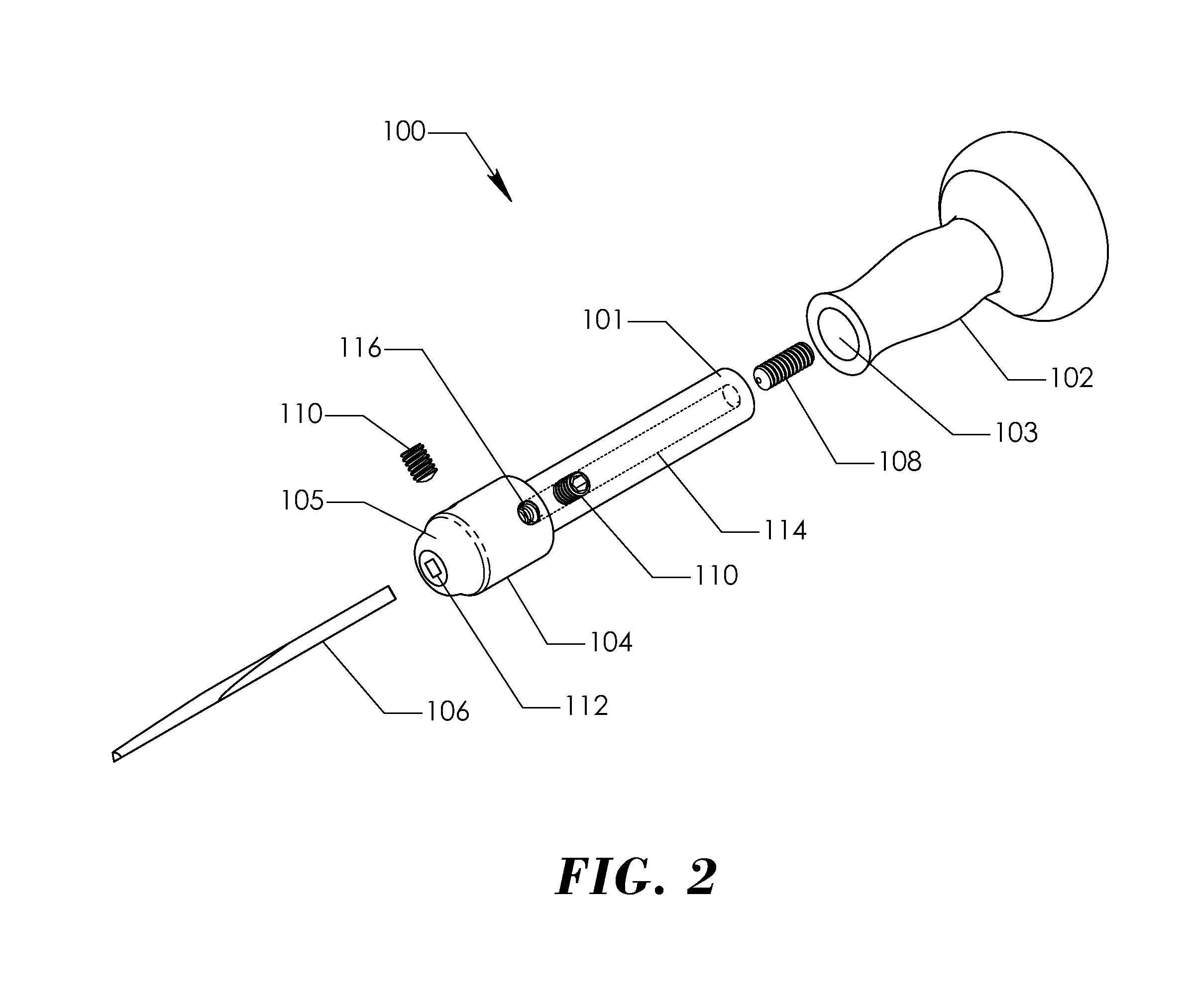
[0048]FIG. 2 illustrat...


PUM

PropertyMeasurementUnit
Lengthaaaaaaaaaa
Pressureaaaaaaaaaa
Shapeaaaaaaaaaa

Abstract

An engraving tool holder for use in delicate engraving operations that provides fine tool length adjustment. The holder further provides adjustment of tool retention pressure. The holder has a bore that extends axially from the rear of the holder toward the front. Within this bore is an adjusting member that establishes the insertion depth of a tool. The tool holder has a tool receiving aperture formed axially and extending from the forward end. The receiving aperture has a substantially similar cross-sectional shape as the tool inserted into the holder. The holder has at least one retention member located adjacent to the forward end and perpendicularly engages the tool along the receiving aperture.

Description

FIELD OF THE INVENTION[0001]The present invention relates to the art of engraving. More particularly, the invention relates to an adjustable engraving tool holder having improved tool control with fine tool adjustment capability.BACKGROUND OF THE INVENTION[0002]The art of engraving has been a distinguished field for centuries. Engraving is typically employed to embellish a vast array of objects. These objects can include jewelry, printing plates, watches, firearms and pocket knives to name a few. Additionally, engraving artwork is commonly found on various forms of currency.[0003]Engraving artwork may take the form of intricate scroll and leaf designs, art-deco designs and a myriad of illustrations. The artwork may further include precious metal inlay, such as gold wire inlay, to intensify the engraving design. Bulino or Banknote style of engraving is another form of engraving that produces pictorial representations of diverse scenes. Engraving is typically executed by cutting desig...

Claims


Application Information

Patent Timeline
IPC IPC(8): B25G3/26B23P11/00
CPCB25G3/26B44B11/02Y10T279/17821Y10T29/49Y10T29/49826
Inventor COVER, RAYMOND ANTHONY
Owner COVER RAYMOND ANTHONY
Why Eureka
Try Eureka