Duty cycle correcting circuit and method of correcting a duty cycle

a duty cycle and correcting circuit technology, applied in the field of semiconductor integrated circuit (ic) apparatus, can solve the problems of reducing the driving ability of the entire driver of the first stage, increasing the fan-out difference between the drivers of the two stages, and all drivers being erroneously operated

Active Publication Date: 2009-12-03
SK HYNIX INC
View PDF7 Cites 13 Cited by
  • Summary
  • Abstract
  • Description
  • Claims
  • Application Information

AI Technical Summary

Benefits of technology

[0010]In one aspect, a duty cycle correcting circuit includes a duty ratio control unit configured to alternately change logical values of a plurality of bits of a pull-up control signal and a plurality of bits of a pull-down control signal in response to a duty ratio detection signal, a duty ratio correcting unit configured to adjust driving abilities of a first driver and a second driver in response to the plurality of bits of the pull-up control signal and the plurality of bits of the pull-down control signal to output a correction clock signal, and a duty ratio detecting unit configured to detect a duty ratio of the correction clock to generate the duty ratio detection signal.
[0011]In another aspect, a du

Problems solved by technology

However, if the driving ability of the pull-up section of the driver of the first stage is minimized, then the driving ability of the entire driver of the fi

Method used


Image

  • Duty cycle correcting circuit and method of correcting a duty cycle
  • Duty cycle correcting circuit and method of correcting a duty cycle
  • Duty cycle correcting circuit and method of correcting a duty cycle

Examples


Embodiment Construction

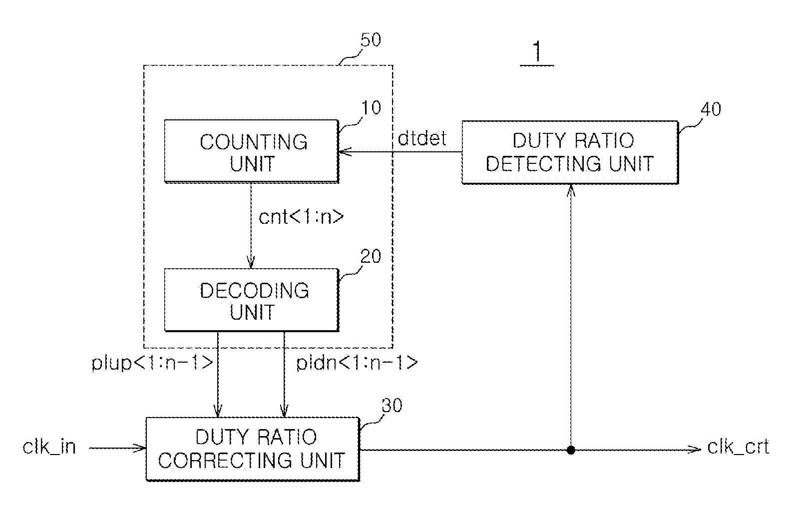
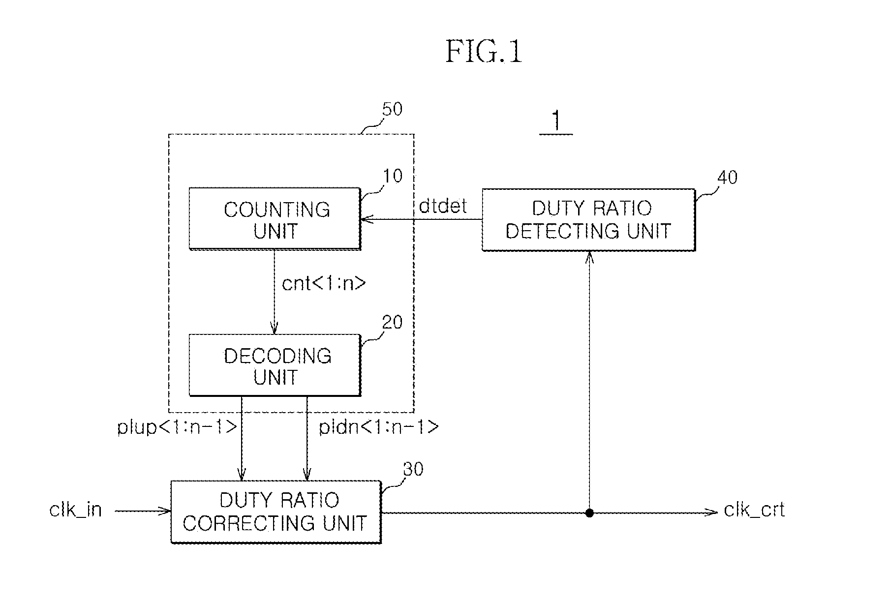
[0020]FIG. 1 is a schematic block diagram of an exemplary duty cycle correcting circuit apparatus according to one embodiment. In FIG. 1, the duty cycle correcting circuit 1 can be configured to include a counting unit 10, a decoding unit 20, a duty ratio correcting unit 30, and a duty ratio detecting unit 40.

[0021]The counting unit 10 can generate n-bits of a counting signal ‘cnt’ in response to a duty ratio detection signal ‘dtdet’. The duty ratio detection signal ‘dtdet’ can be enabled when a low level interval of a correction clock signal ‘clk_crt’ that can be wider than a high level interval thereof. The counting unit 10 can be operated when the duty ratio detection signal ‘dtdet’ is enabled. In the n-bits of the counting signal ‘cnt’ that are generated when the counting unit 10 is operated, a logical value thereof can increase in a predetermined unit, for example, a “1”. When the duty ratio detection signal ‘dtdet’ is disabled, the counting unit 10 can lock the logical value o...


PUM


Abstract

A duty cycle correcting circuit includes a duty ratio control unit configured to alternately change logical values of a plurality of bits of a pull-up control signal and a plurality of bits of a pull-down control signal in response to a duty ratio detection signal, a duty ratio correcting unit configured to adjust driving abilities of a first driver and a second driver in response to the plurality of bits of the pull-up control signal and the plurality of bits of the pull-down control signal to output a correction clock signal, and a duty ratio detecting unit configured to detect a duty ratio of the correction clock to generate the duty ratio detection signal.

Description

CROSS-REFERENCES TO RELATED PATENT APPLICATION[0001]The present application claims priority under 35 U.S.C 119(a) to Korean Application No. 10-2008-0051064, filed on May 30, 2008, in the Korean Intellectual Property Office, which is incorporated herein by reference in its entirety as if set forth in full.BACKGROUND[0002]1. Technical Field[0003]The embodiment described herein relate to a semiconductor integrated circuit (IC) apparatus and a method thereof and, more particularly, to a duty cycle correcting circuit included in a semiconductor IC apparatus and a method of correcting a duty cycle of a clock signal.[0004]2. Related Art[0005]In general, semiconductor IC apparatuses, such as synchronous dynamic random access memory (SDRAM) apparatus, have increased operational speeds by operating using clock signals. For example, a semiconductor IC apparatus includes a clock buffer and buffers an external clock signal to use it inside. In some cases, the semiconductor IC apparatus uses a de...

Claims


Application Information

Patent Timeline
IPC IPC(8): H03K3/017
CPCH03K5/1565G11C8/00H03L7/00
Inventor YUN, WON-JOOLEE, HYUN-WOO
Owner SK HYNIX INC
Why Eureka
Try Eureka