Loop antenna device with large opening area

a technology of loop antenna and opening area, which is applied in the direction of electrically long antennas, non-resonant long antennas, antenna feed intermediates, etc., can solve the problems of inability to improve communication quality, and remain a consideration problem, so as to increase the number of turns and increase the opening area , the effect of small width

Inactive Publication Date: 2009-12-03
ALPS ALPINE CO LTD
View PDF4 Cites 7 Cited by
  • Summary
  • Abstract
  • Description
  • Claims
  • Application Information

AI Technical Summary

Benefits of technology

[0018]Therefore, although the number of turns is increased, the opening area is increased due to the configuration of the other loop with the small width as compared with the above-mentioned case where only the loops horizontally disposed are provided. Therefore, the communication distance of the antenna is lengthened, and the communication quality can be improved.
[0019]Moreover, the parasitic capacitance can be reduced due to the configuration of the one loop with the small height as compared with the above-mentioned case where only the loops vertically disposed are provided. Therefore, the Q value is high, and the magnetic field energy emitted is intensified. Therefore, the communication distance of the antenna is lengthened.
[0020]As a result, the antenna with a long line, the large opening area, and sensitive resonant characteristics can be implemented, and the communication quality of the loop antenna device can be improved.

Problems solved by technology

However, when only the loops horizontally disposed are provided, there is a problem in that the communication quality cannot be improved.
However, even in this case, the communication quality cannot be improved.
However, in the related art, there still remains a problem of the consideration.

Method used


Image

  • Loop antenna device with large opening area
  • Loop antenna device with large opening area
  • Loop antenna device with large opening area

Examples


Embodiment Construction

[0026]Hereinafter, exemplary embodiments of the invention will be described with reference to the accompanying drawings.

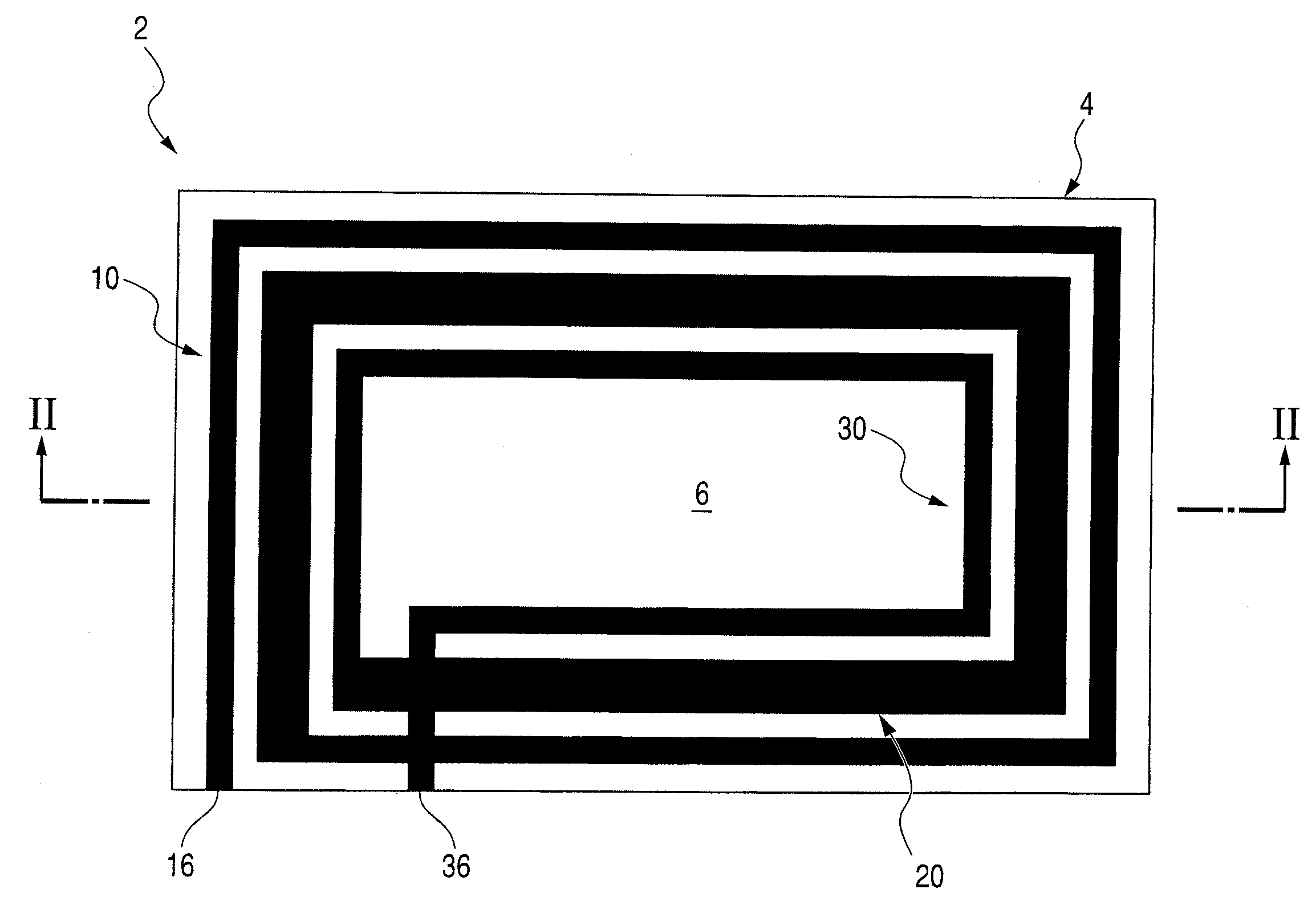
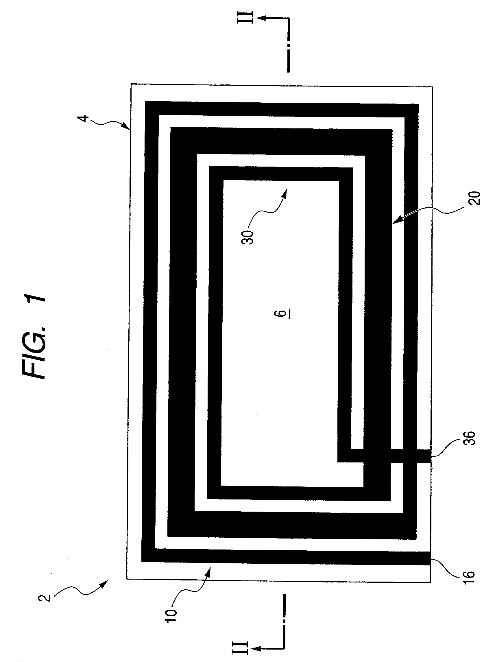
[0027]FIG. 1 is a plan view of a loop antenna device according to an embodiment. The device 2 is used for, for example, an RFID reader / writer.

[0028]The antenna device 2 includes a conductor wound spirally on an insulating substrate 4 that is substantially rectangular.

[0029]Specifically, as illustrated in FIG. 1, the substrate 4 includes a top surface 6 that is substantially rectangular, and four sides of the top surface 6 are connected to form the substantially rectangular shape. Each of the sides is connected to a lower surface having the same area as the top surface 6, and the lower surface opposes the top surface 6.

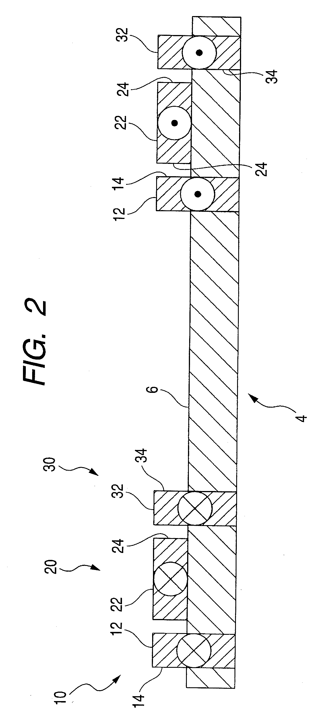
[0030]In addition, on the top surface 6, the conductor having, for example, loops wound three times (3-turn) is disposed.

[0031]The device 2 in this embodiment includes three loops 10, 20, and 30, and the loops 10, 20, and 30 are formed by screen-print...


PUM


Abstract

A loop antenna device is disclosed with an increased number of turns, a large opening area, and a high Q value. The loop antenna device includes: a conductor wound spirally on an insulating substrate, wherein the conductor is constituted by a plurality of loops which are connected and each of which has a substantially rectangular shape with predetermined height and width in a cross-sectional view, and with regard to the adjacent loops of which height portions face each other, a height of the one loop is smaller than a height of the other loop, and a width of the other loop is smaller than a width of the one loop.

Description

CROSS REFERENCE TO RELATED APPLICATIONS[0001]The present invention contains subject matter related to and claims prior to Japanese Patent Application No. 2008-144182 filed in the Japanese Patent Office on Jun. 2, 2008, the entire contents of which is incorporated herein by reference.BACKGROUND[0002]1. Technical Field[0003]The present disclosure relates to a loop antenna device used for a communication device for RFID (radio frequency identification) using, for example, an HF band.[0004]2. Related Art[0005]This type of loop antenna device which is used for, for example, an automatic ticket gate of transportation facilities, receives and transmits a signal by using magnetic field coupling between two antennas.[0006]Specifically, when an IC card of a user passes through a magnetic field generated in an antenna of a reader / writer, electrical resonance occurs, induced current flows through the antenna of the card to activate an IC chip, and a magnetic field in a direction reverse to a ma...

Claims


Application Information

Patent Timeline
Patent Type & Authority Applications(United States)
IPC IPC(8): H01Q11/12
CPCH01Q11/08H01Q9/27
Inventor XI, LI
Owner ALPS ALPINE CO LTD
Why Eureka
Try Eureka