Motion capture system and method for three-dimensional reconfiguring of characteristic point in motion capture system

a technology of motion capture system and characteristic point, which is applied in the field of optical motion capture system, can solve the problems of difficult three-dimensional reconstruction and labeling, large detail of measured data, and extremely small inconvenience to the subject, so as to improve data reliability and fast calculations

Active Publication Date: 2009-12-03
THE UNIV OF TOKYO
View PDF7 Cites 18 Cited by
  • Summary
  • Abstract
  • Description
  • Claims
  • Application Information

AI Technical Summary

Benefits of technology

[0046]Moreover, by separating the three-dimensional reconstruction into local three-dimensional reconstruction processing (for example, processing using groups of three cameras) and surface node integrating processing, it is possible to perform faster calculations and improve data reliability.

Problems solved by technology

However, detailed data including changes in the shape of a body during motion may be required depending on the application, and the extent of detail of the measured data is one important problem.
The marker itself does not generate light and the extent to which the subject is inconvenienced is extremely small.
However, three-dimensional reconstruction and labeling are difficult because of the lack of distinction between markers.
When the number of markers increases, the amount of processing exponentially increases and the likelihood of erroneous recognition also increases.
However, the extent to which the subject is inconvenienced increases because wires are necessary to supply electrical power to the markers.
Further, the number of markers that can be utilized at one time is limited, and measurement of motion of a number of subjects at the same time is difficult.
However, in particular, because of the following reasons, it is difficult to increase the number of markers in optical motion capture methods of the related art.
(1) According to passive optical motion capture of the related art, when markers are arranged in close proximity to each other, the likelihood of errors being made with regards to correlation of the markers between camera images taken from different viewpoints in calculation of three-dimensional positions for the markers increases, and calculation of three-dimensional positions becomes difficult.
However, application to calculation of motion is difficult because processing takes substantial time.
Further, it is also difficult to obtain the same precision as for motion capture.
However, measurement of a physical body in motion is difficult because irradiation of the whole of the subject with a laser takes a certain period of time.
Further, these methods are based on a completely different theory to that of current optical motion capture and their introduction therefore requires replacement of both hardware and software.

Method used


Image

  • Motion capture system and method for three-dimensional reconfiguring of characteristic point in motion capture system
  • Motion capture system and method for three-dimensional reconfiguring of characteristic point in motion capture system
  • Motion capture system and method for three-dimensional reconfiguring of characteristic point in motion capture system

Examples


Embodiment Construction

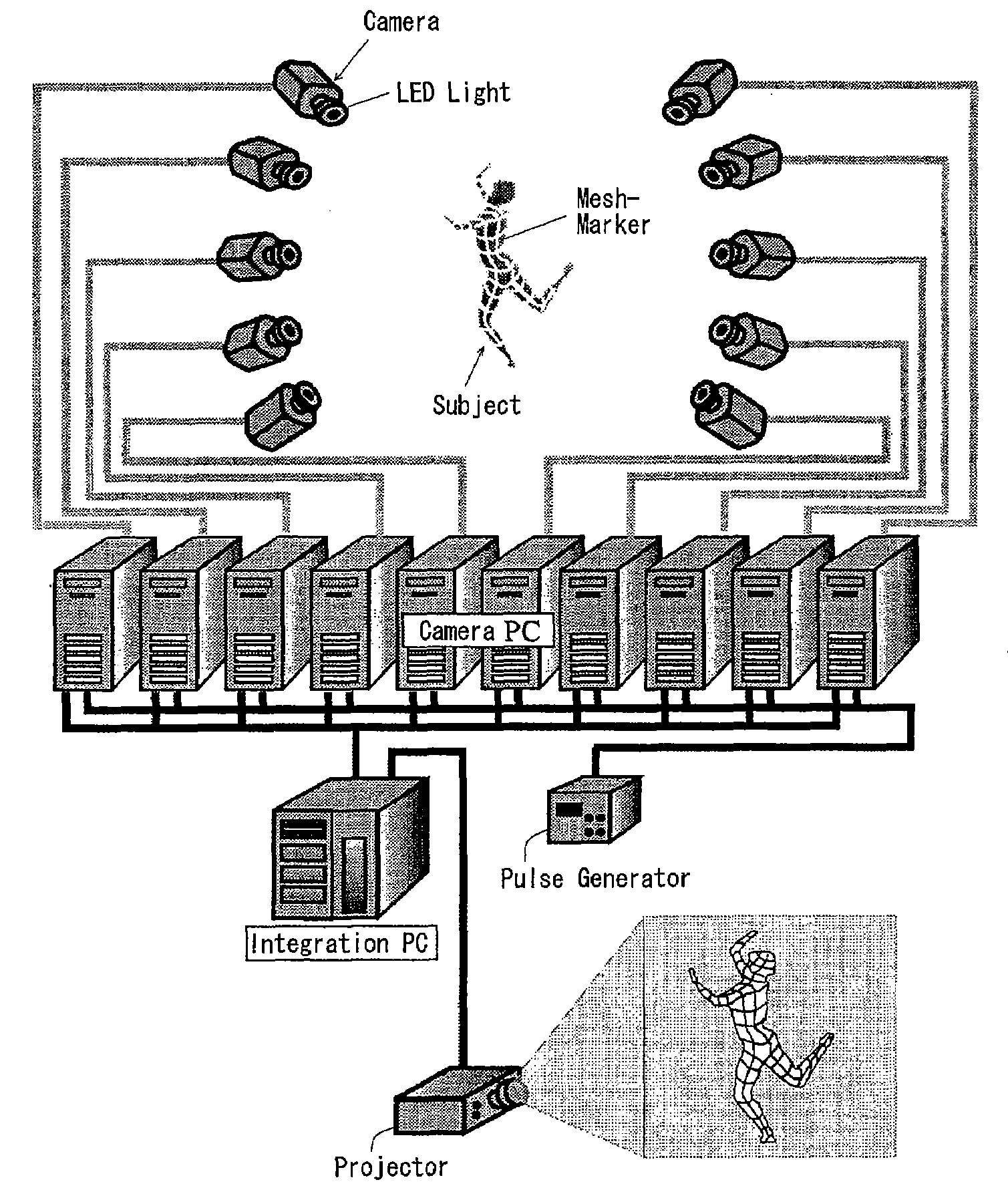
[0077][1] Motion Capture System Utilizing the Connectivity Information of Marker

[0078][1-1] Connectivity Information of Marker

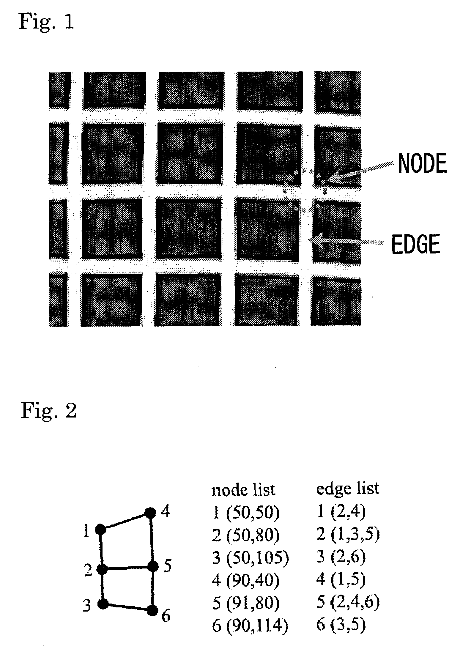
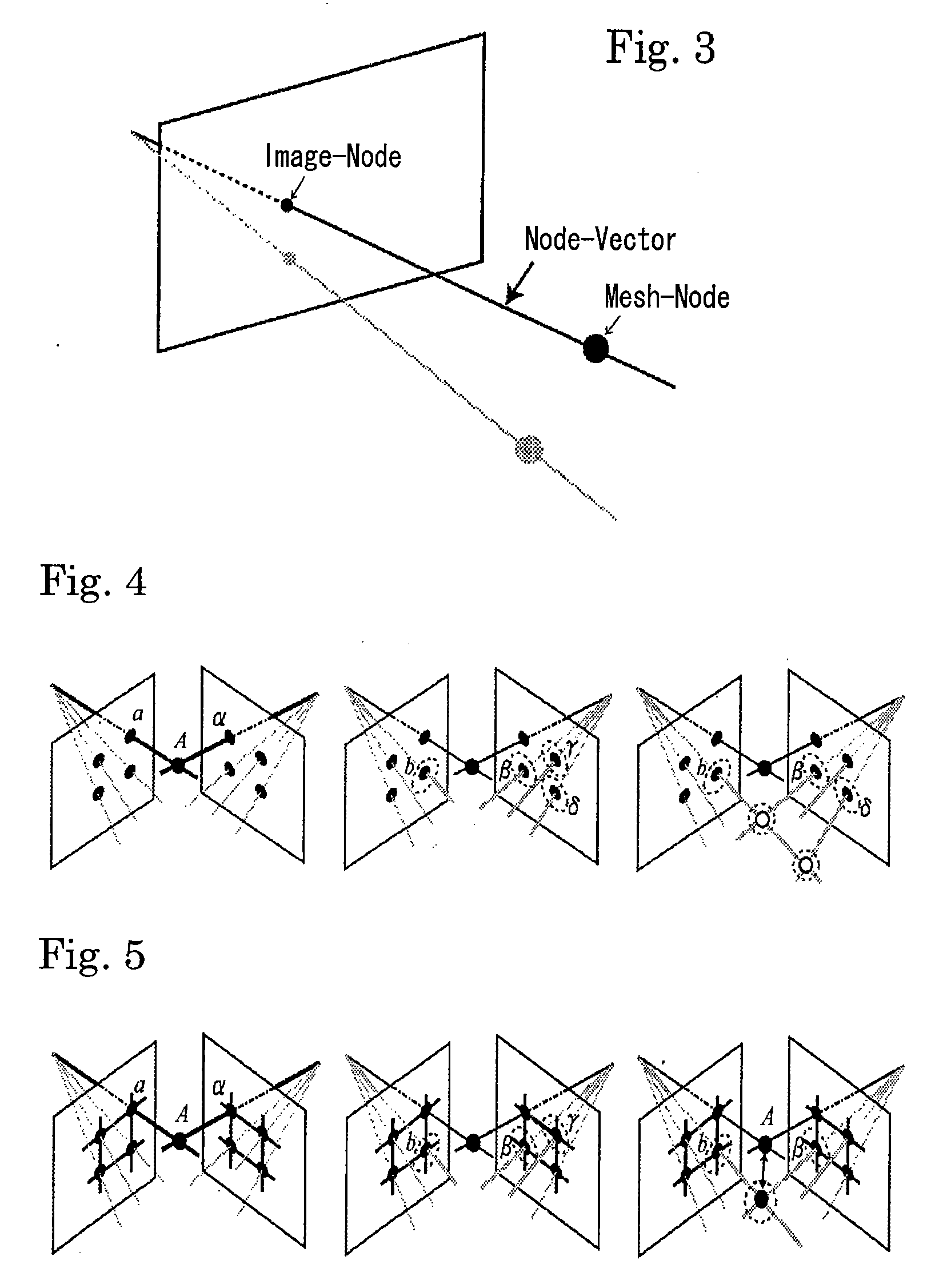
[0079]In the present system, in place of regularly-used spherical markers, marker with the retroreflective tape arranged in mesh forms (hereinafter called the mesh marker) is used. FIG. 1 shows a partial diagrammatic view of a mesh marker. The intersections of the tapes are called nodes and a line connecting two nodes is called an edge. Unlike regularly-used spherical markers, in the mesh marker, respective nodes have connectivity information. The connectivity information relates to the information on which nodes are connected each other by edges. By utilizing the connectivity information of the mesh marker has, the three-dimensional position of nodes can be accurately estimated. The difference of three-dimensional reconstruction methods where the connectivity information is used and where the connectivity information is not used will be discussed as follows....


PUM


Abstract

In an optical motion capture system, it is possible to measure spatially high-dense data by increasing the number of measuring points. In the motion capture system using a mesh marker, intersections of lines for the mesh marker are called nodes and the lines connecting the nodes are called edges. The system includes a plurality of cameras for capturing a two-dimensional image of the mesh marker by imaging a subject having the mesh marker, a node/edge detecting section for detecting node/edge information on the mesh marker from the two-dimensional image captured by the respective cameras, and a three-dimensional reconstructing section for acquiring three-dimensional position information of the nodes by using the node/edge information detected from the plurality of two-dimensional images captured by different cameras.

Description

TECHNICAL FIELD[0001]The present invention relates to an optical motion capture system.BACKGROUND ART[0002]Motion capture technology is utilized in various fields such as industry and medical field as well as in the entertainment field. For example, in the field of computer animation, it is possible to achieve more natural-looking movement by applying movement of humans acquired through motion capture to a computer graphics character. In the field of manufacture and development of computer graphics images relating to multimedia and entertainment such as movies and games, motion capture may be indispensable technology. In addition, motion capture technology is also actively employed in various fields such as robotics, biomechanics, sports science, and medical field. Motion capture technology may be optical, magnetic, or mechanical etc. Optical motion capture depends on the type of marker and may be classified into passive optical motion capture and active optical motion capture.[0003...

Claims


Application Information

Patent Timeline
Patent Type & Authority Applications(United States)
IPC IPC(8): H04N13/00G09G5/00G06K9/00
CPCG06T7/0065G06T2207/30208G06T2207/10021G06T7/0077G06T7/55G06T7/596
Inventor NAKAMURA, YOSHIHIKOYAMANE, KATSUTANIE, HIROAKI
Owner THE UNIV OF TOKYO
Why Eureka
Try Eureka