Chassis, electronic equipment and manufacturing method for chassis

Active Publication Date: 2009-12-03
KK TOSHIBA
View PDF2 Cites 35 Cited by
  • Summary
  • Abstract
  • Description
  • Claims
  • Application Information

AI Technical Summary

Benefits of technology

[0015]According to another aspect of the invention, there is provided a method for manufacturing a chassis including sealing an outer edge of a flat plate portion including a first major surface and a second major surface facing the first major surface with a resin, the method for man

Problems solved by technology

However, wall thickness reduction is limited in consideration of fluency of flow of the molten nonferrous metal alloy.
This means that there are limitations in weight reduction, slimming down and downsizing of the electronic equipment based on the chassis formed by the die-cast molding method.
However, in the technique disclosed in JP-A 2005-10699(Kokai), it is not considered that a pressure during the resin filling causes the core in a seal portion to deform and become misaligned.
Hence,

Method used


Image

  • Chassis, electronic equipment and manufacturing method for chassis
  • Chassis, electronic equipment and manufacturing method for chassis
  • Chassis, electronic equipment and manufacturing method for chassis

Examples


Example

[0031]Embodiments of the invention will now be described with reference to the drawings. In the drawings, like components are labeled with like reference numerals, and the detailed description thereof is omitted as appropriate.

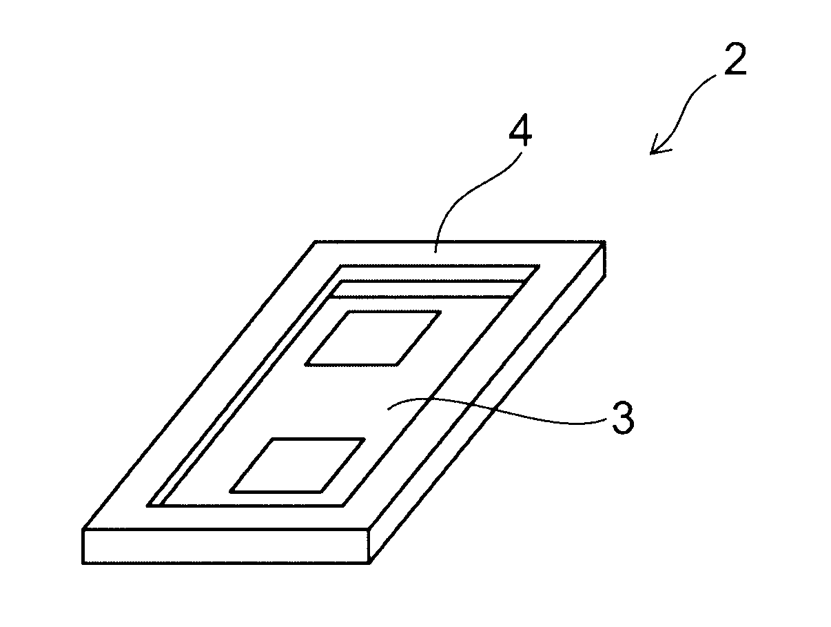
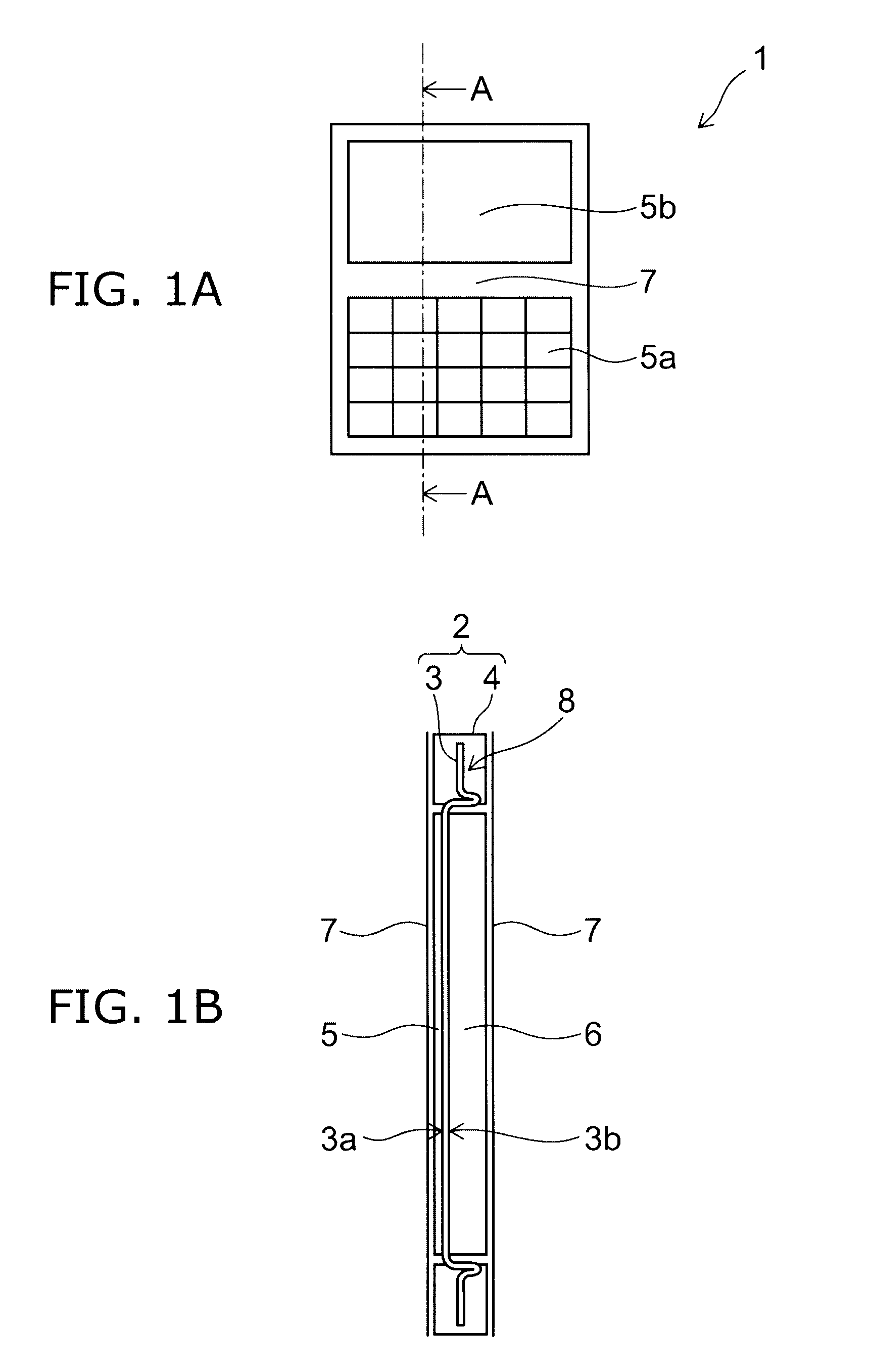
[0032]FIGS. 1A and 1B are schematic views for illustrating an electronic equipment according to an embodiment of the invention. FIG. 1A shows a front view of the electronic equipment and FIG. 1B shows a cross-sectional view taken in a direction of the arrows A-A of FIG. 1A.

[0033]Here, the electronic equipment illustrated in FIGS. 1A and 1B illustrates a personal digital equipment provided with an input mechanism such as a key switch and an output mechanism such as a flat display panel as an example of the electronic equipment according to this embodiment of the invention. The personal digital equipment can be illustrated as a portable computer, various portable audio player and video player, a personal digital assistant such as PDA (Personal Digital Assistant)...


PUM


Abstract

A chassis includes: a flat plate portion including a first major surface and a second major surface facing the first major surface; a protruding portion provided on an outer edge of the flat plate portion and protruding in a direction crossing the first and second major surfaces; and a seal portion provided on the outer edge of the flat plate portion.

Description

CROSS-REFERENCE TO RELATED APPLICATIONS[0001]This application is based upon and claims the benefit of priority from the prior Japanese Patent Application No. 2008-145519, filed on Jun. 3, 2008 and the prior Japanese Patent Application No. 2008-224830, filed on Sep. 2, 2008; the entire contents of which are incorporated herein by reference.BACKGROUND OF THE INVENTION[0002]1. Field of the Invention[0003]This invention relates to a chassis, an electronic equipment and a method for manufacturing the chassis.[0004]2. Background Art[0005]It is necessary for an electronic equipment incorporating an electronic component such as a display panel (for example, flat display panel such as liquid crystal display panel and organic EL display panel), a switch and a circuit board that the electronic component is not broken even if an external force and a mechanical impact are applied. Hence, a chassis of the electronic equipment is desired to have high rigidity so that the incorporated electronic co...

Claims


Application Information

Patent Timeline
IPC IPC(8): H05K7/00
CPCH04M1/0249H05K5/0017H04M1/185
Inventor MORIMOTO, JUNAOKI, YUKINORINISHIKAWA, SHOUICHI
Owner KK TOSHIBA
Why Eureka
Try Eureka