Apparatus and method of optimizing power system efficiency using a power loss model

a power system and efficiency optimization technology, applied in the direction of electric variable regulation, process and machine control, instruments, etc., can solve the problems of reducing the efficiency of the primary converter, affecting the efficiency of the overall system, and raising the efficiency of the secondary regulator, so as to improve the efficiency of the overall subsystem, and maximize the efficiency of the subsystem

Active Publication Date: 2009-12-03
BEL POWER SOLUTIONS INC
View PDF34 Cites 54 Cited by
  • Summary
  • Abstract
  • Description
  • Claims
  • Application Information

AI Technical Summary

Benefits of technology

[0016]The processor then proceeds to evaluate the effect on the goal function of small changes to the operating parameters of each of the components with the objective of minimizing the goal function and thereby maximizing the efficiency of the subsystem. If the processor determines, for example, that lowering the intermediate bus voltage will result in an improvement of overall subsystem efficiency, it will then command that change to the primary power converter to cause its output voltage to change to the optimal value calculated by the processor. The measurement, calculation, and command cycle will be repeated at a rate set by the demands of the application for which the power subsystem is used. This process results in the dynamic optimization of the efficiency of the subsystem, taking into account changes in loads or operating modes.
[0017]Sometimes, commanding the system to change an intermediate voltage or other parameter might have negative consequences, such as reducing the input voltage to the secondary converters below their recommended levels. To address this, an alternative embodiment of a power subsystem in accordance with the invention also includes a set of subsystem constraint data that is stored in the memory unit. This data may include limits on such parameters as the input voltage, output voltage, temperature, and current, among others, that should not be exceeded in applying a change of state to the system. ...

Problems solved by technology

Thus, it is clear that the selection of the intermediate voltage will affect the efficiency of the overall system.
Lowering the intermediate voltage will reduce the efficiency of the primary converter but raise the efficiency of the secondary regulators.
Similarly, although the efficiency of both the primary converter and the secondary regulators decrease as the temperature increases, operating a fan or other active cooling system consumes power and thus reduces system efficiency.
However, in many cases, it is impractical to measure the power loss of a power conversion device directly with enough accuracy to enable effective control.
For example, a typ...

Method used


Image

  • Apparatus and method of optimizing power system efficiency using a power loss model
  • Apparatus and method of optimizing power system efficiency using a power loss model
  • Apparatus and method of optimizing power system efficiency using a power loss model

Examples


Embodiment Construction

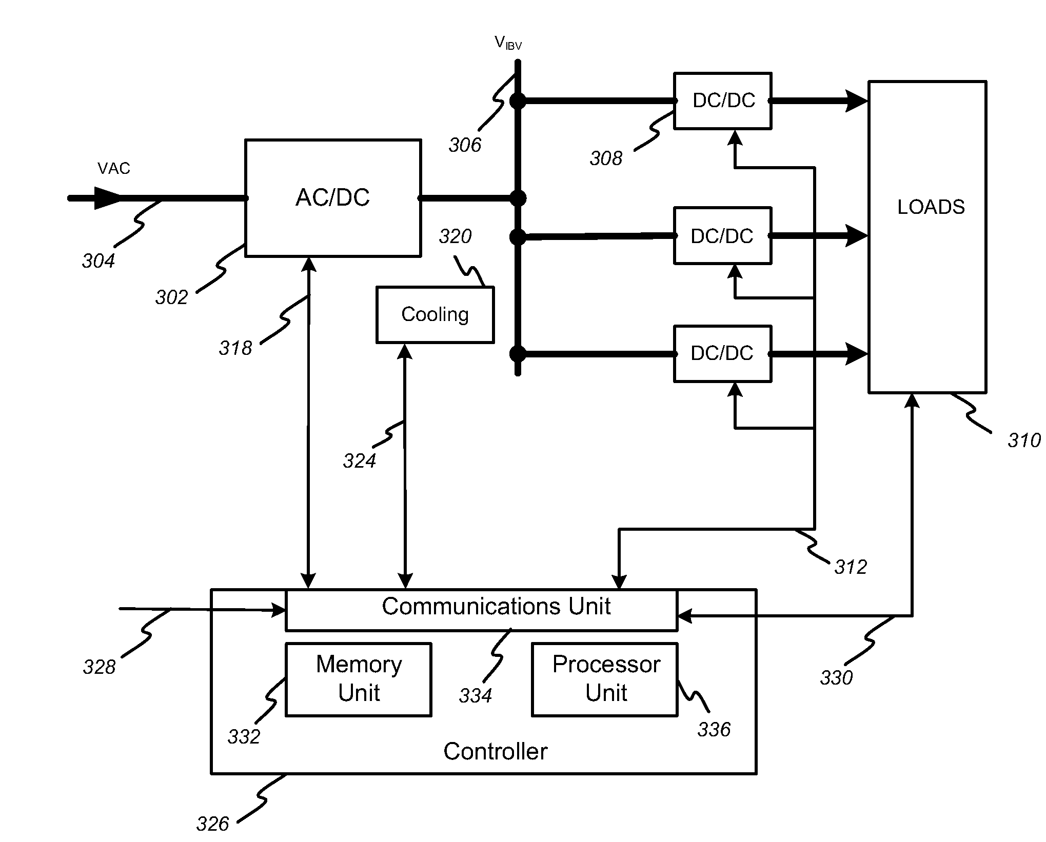
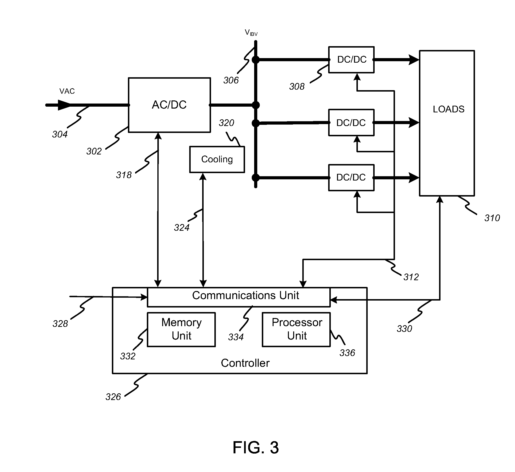
[0027]The invention provides a power subsystem architecture and method of device power-loss characterization and monitoring that enables the dynamic control of operating set points to achieve high efficiency over a wide range of system operating conditions. In the detailed description that follows, like element numerals are used to indicate like elements appearing in one or more of the figures.

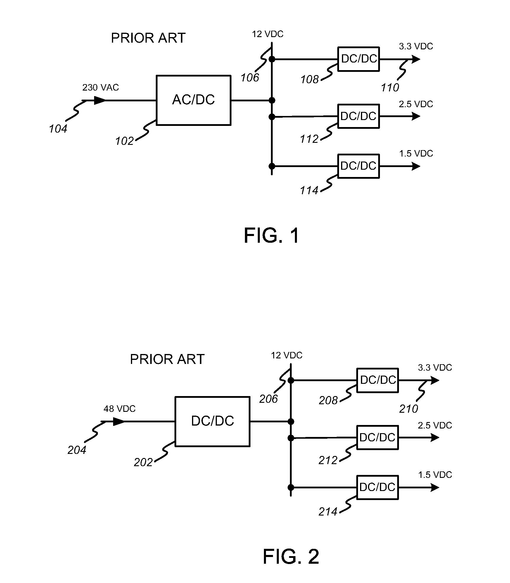
[0028]Conventional distributed power subsystem architectures are depicted in the block diagrams of FIGS. 1 and 2. In FIG. 1, an AC / DC converter 102 is used to convert a 230-volt primary AC bus 104 to a 12-volt intermediate DC bus 106. The intermediate bus 106 is distributed to secondary converters or regulators 108, 112, and 114 in order to generate the specific voltages, e.g. 110, required by the system components. FIG. 2 depicts a similar system that uses a primary DC / DC converter 202 to convert a 48-volt primary DC bus 204 to a 12-volt intermediate bus 202. In both FIG. 1 and FIG. 2, the vo...


PUM


Abstract

A power subsystem is actively optimized to improve total subsystem efficiency in a way that is responsive to changes in load requirements, power supply variations, and subsystem temperature variations. Detailed, multidimensional power loss models are developed for constituent devices which are then combined into a power subsystem containing a controller and circuity for measuring device operating parameters such as input and output voltage, output current, and temperature. Operating parameters are continually monitored, and set points are correspondingly changed based on the detailed power loss models to achieve maximum overall efficiency for the instantaneous operating state of the system.

Description

BACKGROUND OF THE INVENTION[0001]1. Field of the Invention[0002]The present invention relates to power subsystem architectures, and more particularly, to a power subsystem that actively provides energy management and control of subsystem efficiency by using power-loss models of power devices.[0003]2. Description of Related Art[0004]It is well known in the art to use a distributed power subsystem architecture comprising multiple power conversion stages to provide necessary bus voltages for microprocessors, memories, and other electronic devices. A conventional system might operate from an alternating current (AC) primary voltage source that is converted to an intermediate direct current (DC) bus voltage using an isolated AC / DC converter. This intermediate DC bus voltage is then typically distributed throughout the system and converted locally by secondary DC / DC converters to lower voltages matched to the input voltage requirements of system loads. Alternatively, a system might operat...

Claims


Application Information

Patent Timeline
IPC IPC(8): H02J1/10
CPCH02J1/08H02M3/28H02M2001/0048H02J2001/008H02M2001/008Y02B70/1491H02M2001/0012H02M2001/007H02J1/082H02M1/0012H02M1/0048H02M1/007H02M1/008Y02B70/10
Inventor CHAPUIS, ALAIN
Owner BEL POWER SOLUTIONS INC
Why Eureka
Try Eureka