
Method and apparatus for detecting a fault in a brushless exciter for a generator

a brushless excitation and fault detector technology, applied in the direction of motor/generator/converter stopper, dynamo-electric converter control, instruments, etc., can solve the problem of difficult to reliably detect a fault in one diode, the ability of the rectifier to convert ac to dc power is affected by single diode, and the failure of one diode to substantially reduce the ability of the rectifier to achieve the effect of dc power conversion

Inactive Publication Date: 2009-12-03
GENERAL ELECTRIC CO
View PDF12 Cites 27 Cited by
  • Summary
  • Abstract
  • Description
  • Claims
  • Application Information

AI Technical Summary

Problems solved by technology

A fault in a diode of the rectifier can impair the conversion of AC to DC by the rectifier.
It is generally difficult to reliably detect a fault in one diode, due to the presence of redundant diodes.
The failure of a single diode may not substantially reduce the ability of the rectifier to convert AC to DC power.
The failure of two or more diodes in series can impair the conversion of AC to DC, lead to a failure of the rectifier and result in an unscheduled shutdown of the electrical machine.

Method used


Image

  • Method and apparatus for detecting a fault in a brushless exciter for a generator
  • Method and apparatus for detecting a fault in a brushless exciter for a generator
  • Method and apparatus for detecting a fault in a brushless exciter for a generator

Examples


Embodiment Construction

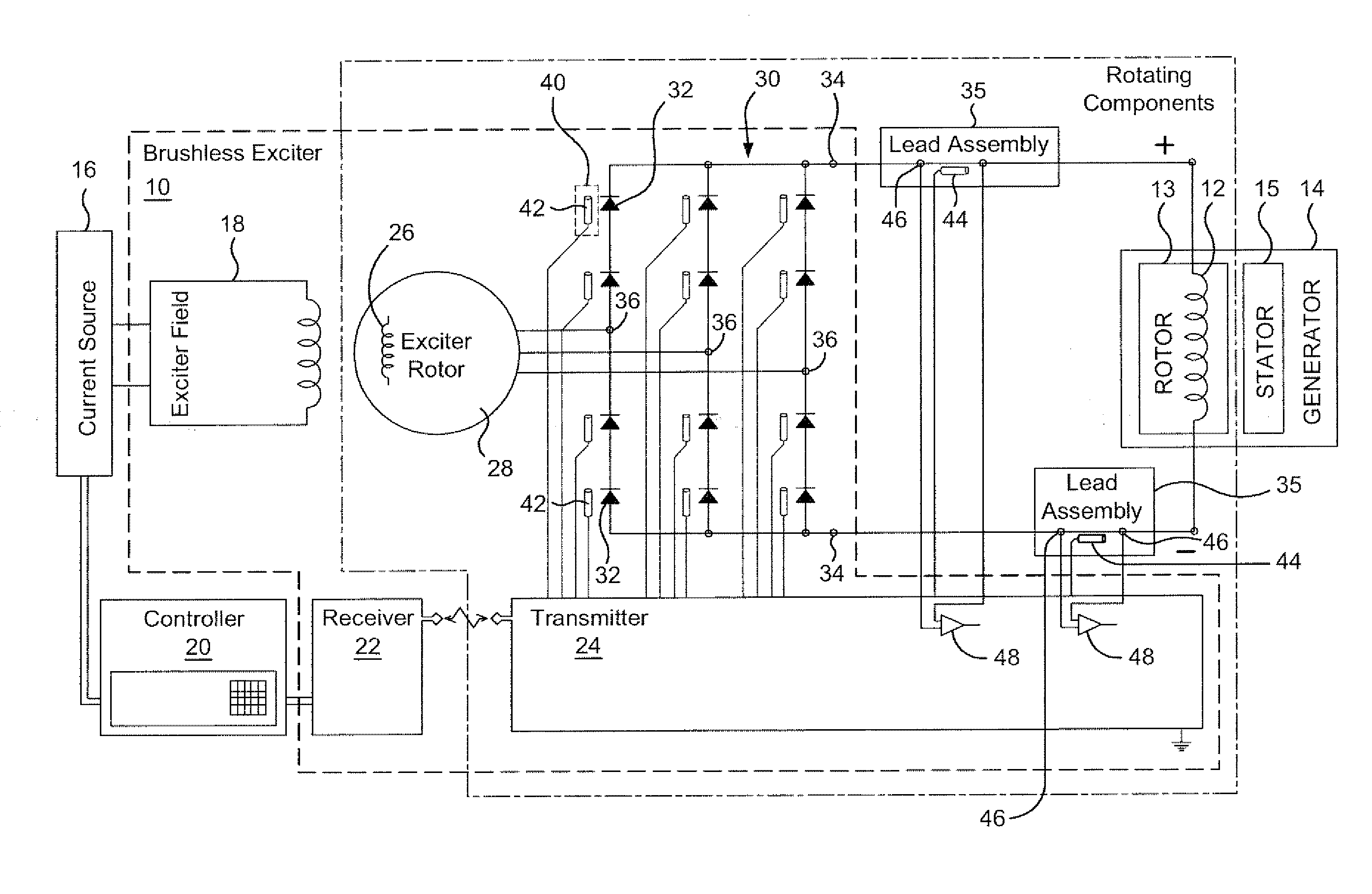
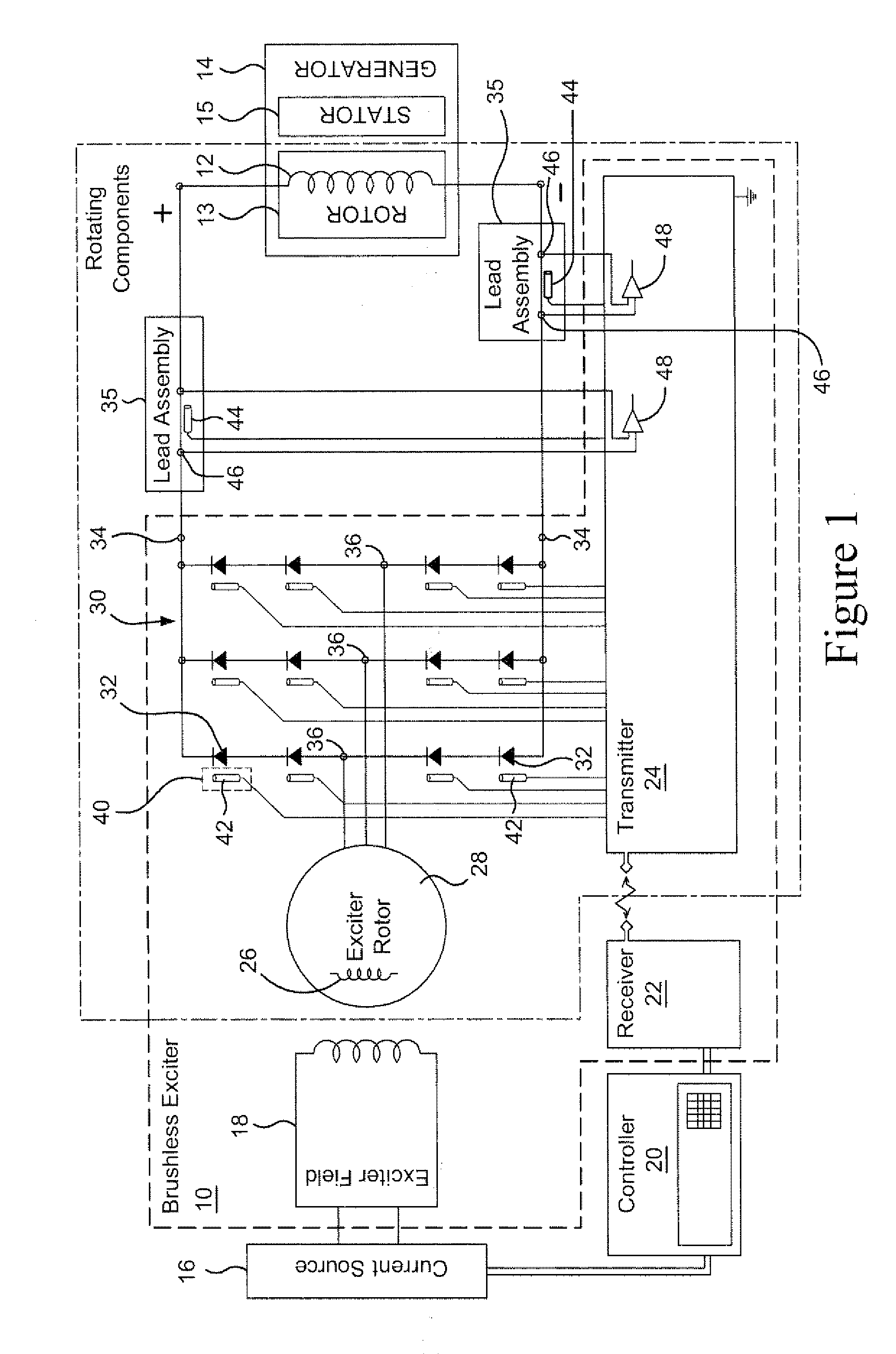
[0011]FIG. 1 is a schematic view of an exemplary generator brushless excitation system 10 for providing excitation power to the field coils 12 of the rotor 13 of an alternating current (AC) generator 14, such as a synchronous generator. The components of the brushless excitation system 10 are within the dotted line box with uniform dashes shown in FIG. 1. The components within the dot-dash line rotate with the rotor 13 of the generator 14.

[0012]The AC generator 14 may be a three-phase synchronous generator providing electrical power for an electric power utility, such as by providing power at a frequency and current level suitable for an electric power grid serving homes, businesses and other facilities. As the rotor 13 turns, an electromagnetic field formed by the field coils 12 induces a current in the stator 15 of the generator. Alternatively, the brushless excitation system disclosed herein may be applied to an electrically-driven motor.

[0013]An electric power source 16 provides...


PUM


Abstract

A method of operating an electrical machine including: providing a brushless excitation system including a diode rectifier having at least one diode; sensing heat energy generated by the at least one diode; detecting a deviation of the generated heat energy from the at least one diode, and generating a signal indicating a failed or faulty diode if the deviation in generated heat energy exceeds a predetermined threshold deviation level.

Description

BACKGROUND OF THE INVENTION[0001]The present invention relates to brushless excitation systems for rotating electrical machines and, particularly, relates to a temperature sensing fault detector for a brushless excitation system.[0002]A brushless excitation system (or more simply a “brushless exciter”) applies a direct current (DC) to the field coils of a rotor in an electrical machine. The current in the rotor field coils generates an electromagnetic field that induces current in, for example, the coils of a stator surrounding the rotor and in a generator producing AC current. Alternatively, the electromagnetic field from the rotor field coils may be used to turn the rotor of a motor.[0003]Typically, a brushless excitation system is mounted on and rotates with the rotor of the electrical machine. The brushless excitation system includes a rotating armature and a diode rectifier, which may be configured as a diode wheel. Alternating current (AC) generated within the rotating armatur...

Claims


Application Information

Patent Timeline
IPC IPC(8): H02K11/00G01K7/16
CPCH02H7/065H02P29/0088H02P9/302H02P29/68H02K11/25G01R31/343H02K11/042H02M1/32H02H5/04H02H7/08H02H7/10
Inventor FISH, WILLIAM E.
Owner GENERAL ELECTRIC CO
Learn More