Nuclear reactor alignment plate configuration

a technology of alignment plate and nuclear reactor, applied in the direction of climate sustainability, greenhouse gas reduction, containment, etc., to achieve the effect of small clearan

Active Publication Date: 2009-12-03
WESTINGHOUSE ELECTRIC CORP
View PDF4 Cites 2 Cited by
  • Summary
  • Abstract
  • Description
  • Claims
  • Application Information

AI Technical Summary

Benefits of technology

[0010]Preferably, the alignment plate is attached to the inner surface of the core barrel and a reinforcing pad is disposed on the outside of the core barrel and attached to the alignment plate through the core barrel. In one embodiment, the reinforcement pad is attached to the alignment plate with at least two dowel pins that engage the reinforcement pad and the alignment plate through the core barrel. Preferably, the dowel pins are shrunk fit into the reinforcement pad, core barrel and alignment plate. The dowel pins desirably are positioned in spaced relationship with each other, one on top of the other; the top dowel pin is shrink-fitted to holes in both the core barrel and alignment plate, thus anchoring the alignment plate to the core barrel at this location. The bottom dowel hole in the alignment plate is designed to accommodate differential axial thermal growth between the core barrel and the alignment plate. This is accomplished by machining flat surfaces on the vertical faces of the dowel pins and alignment plate, and by enlarging one of the dowel pin holes in the alignment plate so that a gap exists between a top and bottom surface of one of the dowel pins and the alignment plate, allowing differential thermal growth in the vertical direction.

Problems solved by technology

This is particularly challenging when one considers the thermal expansion and contraction that has to be accommodated through power ramp-up and cool down sequences, where temperatures can vary between 50° F.

Method used


Image

  • Nuclear reactor alignment plate configuration
  • Nuclear reactor alignment plate configuration
  • Nuclear reactor alignment plate configuration

Examples


Embodiment Construction

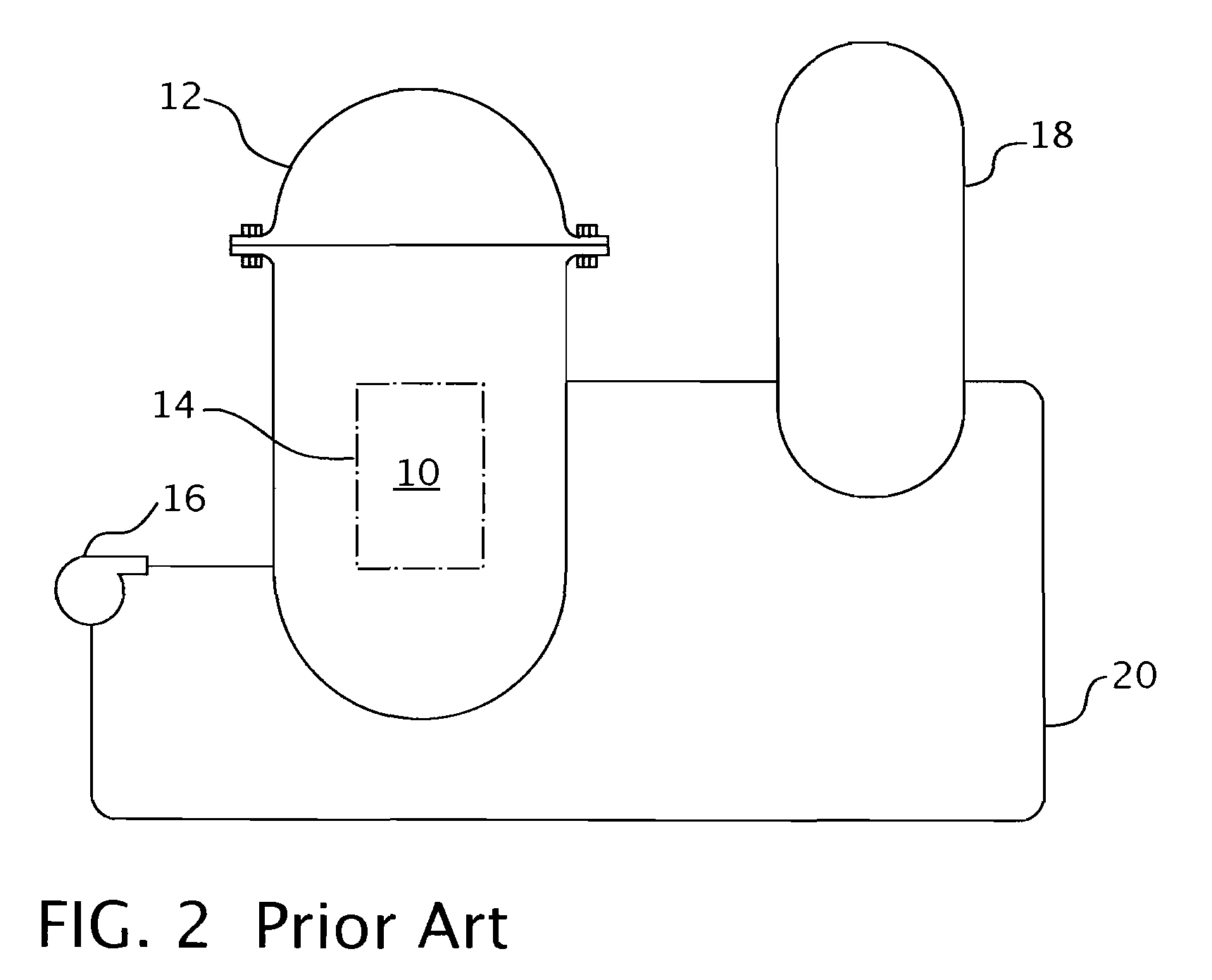
[0019]Referring now to the drawings, FIG. 2 shows a simplified nuclear reactor primary system, including a generally cylindrical reactor pressure vessel (10) having a closure head (12) enclosing a nuclear core (14). A liquid reactor coolant, such as water, is pumped into the vessel (10) by pumps (16) through the core (14) where heat energy is absorbed and is discharged to a heat exchanger, typically referred to as a steam generator, in which heat is transferred to a utilization circuit (not shown), such as a steam-driven turbine generator. The reactor coolant is then returned to the pump (16), completing the primary loop. Typically, a plurality of the above-described loops are connected to a single reactor vessel (10) by reactor coolant piping (20).

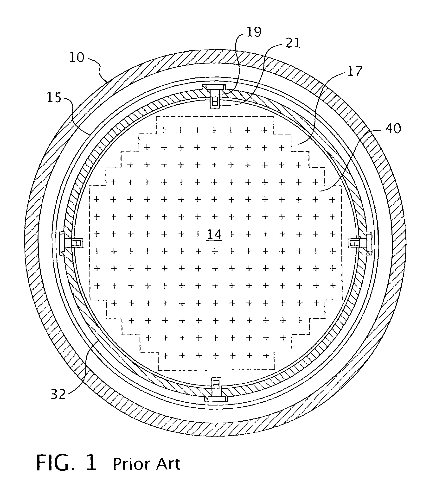
[0020]An exemplary reactor design is shown in more detail in FIG. 3. In addition to a core (14) comprised of a plurality of parallel, vertical co-extending fuel assemblies (22), for purposes of this description, the other vessel internal ...


PUM


Abstract

An alignment plate that is attached to a core barrel of a pressurized water reactor and fits within slots within a top plate of a lower core shroud and upper core plate to maintain lateral alignment of the reactor internals. The alignment plate is connected to the core barrel through two vertically-spaced dowel pins that extend from the outside surface of the core barrel through a reinforcement pad and into corresponding holes in the alignment plate. Additionally, threaded fasteners are inserted around the perimeter of the reinforcement pad and into the alignment plate to further secure the alignment plate to the core barrel. A fillet weld also is deposited around the perimeter of the reinforcement pad. To accommodate thermal growth between the alignment plate and the core barrel, a gap is left above, below and at both sides of one of the dowel pins in the alignment plate holes through which the dowel pins pass.

Description

CROSS-REFERENCE TO RELATED APPLICATIONS[0001]This application claims priority to U.S. Provisional Patent Application No. 60 / 883,072, filed on Jan. 2, 2007.GOVERNMENT INTEREST[0002]This invention was made with government support under Contract No. DE-FC07-051D14636 awarded by the Department of Energy. The government has certain rights in this invention.BACKGROUND OF THE INVENTION[0003]1. Field of the Invention[0004]The present invention relates generally to nuclear reactor internals, more specifically to apparatus for maintaining the alignment of the nuclear reactor internals while permitting thermal growth.[0005]2. Description of Related Art[0006]The primary side of nuclear reactor power generating systems which are cooled with water under pressure comprises a closed circuit which is isolated from and in heat-exchange relationship with a secondary side for the production of useful energy. The primary side comprises the reactor vessel enclosing a core supporting a plurality of fuel a...

Claims


Application Information

Patent Timeline
IPC IPC(8): G21C13/00
CPCG21C13/024Y02E30/40G21C19/19Y02E30/30
Inventor ALTMAN, DAVID A.FORSYTH, DAVID R.SMITH, RICHARD E.SINGLETON, NORMAN R.
Owner WESTINGHOUSE ELECTRIC CORP
Why Eureka
Try Eureka