Vehicle-mounted information system, and data gathering method in diagnostic equipment

a technology of information system and vehicle, applied in the field of vehicle-mounted information system, can solve the problems of increased inability to needless data transmission to the network, and troublesome vehicle operation, and achieve the effect of successfully reducing the load of in-vehicle network

Inactive Publication Date: 2009-12-03
HITACHI LTD
View PDF13 Cites 24 Cited by
  • Summary
  • Abstract
  • Description
  • Claims
  • Application Information

AI Technical Summary

Benefits of technology

[0009]According to the teaching herein, the diagnostic equipment coupled to the in-vehicle network makes an inquiry about internal information (e.g., whether or not there is a memory area available for logging) with respect to each of a plurality of ECUs, and when any of the ECUs forwarding back a response of “memory area yes” is determined as being defective, notifies a defect message, and gathers the internal information from any of the ECUs that has been logged with the internal information. With such a configuration, the load of the in-vehicle network can be successfully reduced, and any data needed for defect diagnosis can be favorably gathered.

Problems solved by technology

The problem with such a technology is the increase of the load of an in-vehicle network.
Moreover, when the ECU is defective, there is a possibility of needless data transmission to the network.
If this is the case, exchange of data needed for vehicle control cannot be completed correctly between the ECU and others, thereby possibly causing troubles for running of the vehicle.
However, not all of the ECUs in the vehicle have a memory enough for accumulating therein the sensor information as such, thereby possibly requiring to modify the hardware and software configurations.

Method used


Image

  • Vehicle-mounted information system, and data gathering method in diagnostic equipment
  • Vehicle-mounted information system, and data gathering method in diagnostic equipment
  • Vehicle-mounted information system, and data gathering method in diagnostic equipment

Examples


Embodiment Construction

[0022]By referring to FIGS. 1 to 11, examples are described.

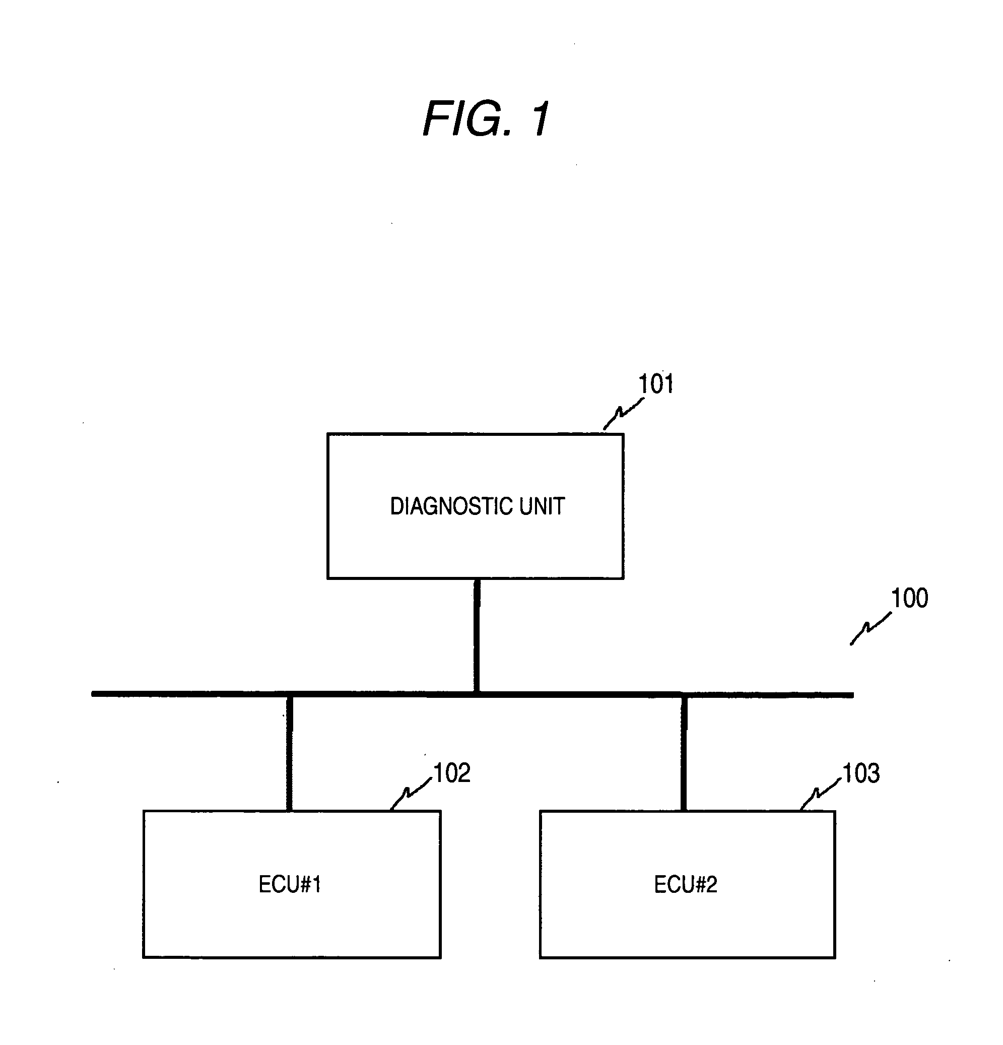
[0023]FIG. 1 shows an exemplary configuration of a vehicle system in an embodiment.

[0024]A diagnostic equipment 101 is coupled to ECUs 102 and 103 over a vehicle network 100. The ECUs 102 and 103 exchange control information with each other over the vehicle network 100. When the ECU 102 is an engine controller unit, and when the ECU 103 is an AT (Automatic Transmission) controller unit, for example, the ECU 103 forwards an AT shift signal as the control information, and upon reception of the signal, the ECU 102 controls the engine in terms of the rotation frequency. The vehicle network is exemplified by CAN (Controller Area Network).

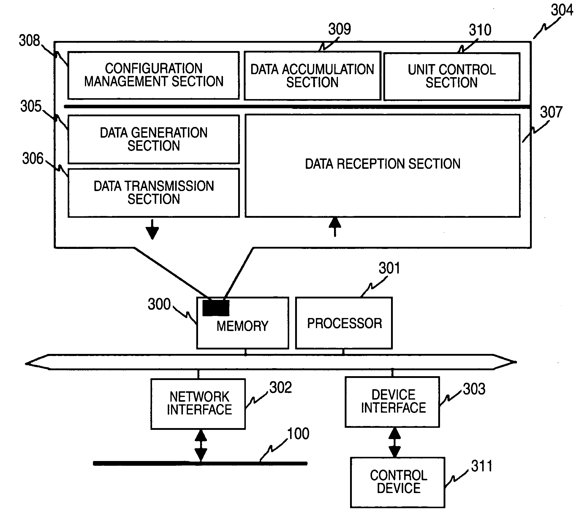
[0025]The ECUs 102 and 103 each have a unit identifier for identification thereof. In FIG. 1 example, the unit identifier of the ECU 102 is ID#1, and the unit identifier of the ECU 103 is ID#2. The diagnostic equipment 101 periodically accumulates control information thereinto or into a nonvolat...


PUM


Abstract

A diagnostic equipment coupled to a vehicle network makes an inquiry about internal information, e.g., yes or no whether there is a logging-available memory area, with respect to each of a plurality of ECUs, and only to any of the ECUs making a response of yes, e.g., having such a memory area, a notification is made when some defect is observed. The internal information is then gathered from the ECU, and in response to an inquiry about the internal information coming from the diagnostic equipment, the ECU forwards back information about yes or no for logging thereto. When the ECU is available for logging, log data that has been periodically accumulated is forwarded back as a response with respect to a retrieval request therefor from the diagnostic equipment.

Description

INCORPORATION BY REFERENCE[0001]This application claims priority based on a Japanese patent application, No. 2008-141866 filed on May 30, 2008, the entire contents of which are incorporated herein by reference.BACKGROUND[0002]The present invention relates to a vehicle-mounted network system and, more specifically, to a system that provides means for gathering data from an ECU (electronic control unit) in a diagnostic equipment.[0003]A vehicle system is of an autonomous decentralized type in which an ECU coupled to a vehicle network broadcasts information needed for any other ECUs, and operates to capture any information needed for its own. Information technology (IT) has been progressing to the field of vehicles, e.g., a large number of ECUs achieve their cooperative control through exchange of vehicle control information over a vehicle network. With the improvement of performance in the vehicles, the number of the ECUs for mounting to the vehicles is increased, and thus data flowin...

Claims


Application Information

Patent Timeline
Patent Type & Authority Applications(United States)
IPC IPC(8): G06F7/00
CPCG07C5/008G07C2205/02G07C5/085
Inventor TANIGAWA, KEIKOSHIMURA, AKITOSHI
Owner HITACHI LTD
Why Eureka
Try Eureka