Method for Operating an Internal Combustion Engine

a technology of internal combustion engine and operating method, which is applied in the direction of electrical control, process and machine control, instruments, etc., can solve the problems of increasing general applicable and non-valve-specific corrections, increasing the cost of manufacturing the injector, and increasing the cost of overall operation of the internal combustion engine. , to achieve the effect of increasing the overall operational reliability of the internal combustion engine, ensuring the effect of torque and running smoothness

Inactive Publication Date: 2009-12-03
ROBERT BOSCH GMBH
View PDF3 Cites 12 Cited by
  • Summary
  • Abstract
  • Description
  • Claims
  • Application Information

AI Technical Summary

Benefits of technology

[0008]In the method according to the present invention, the injector test is barely or not at all apparent to the user of the internal combustion engine, since the total injection quantity is largely constant at least during a portion of the test, and the torque and running smoothness therefore also remain the same. As a result, the test may be carried out frequently, which increases the operational reliability of the internal combustion engine overall.
[0009]According to a first refinement, it is proposed that a deviation of a variable characterizing an actual air / fuel mixture, induced by successively shortening the duration of the measured injection, from a variable characterizing a setpoint air / fuel mixture, be detected, and the deviation or a characteristic curve of the injector is adjusted or corrected. The injected fuel quantity is therefore reliably detected in the low-volume range, in which a deviation of the actually injected actual fuel quantity from the setpoint fuel quantity, which is determined on the basis of the applied characteristic curve, is impermissibly large for an individual injector. The method is equally suitable for both internal combustion engines having intake manifold injection and for internal combustion engines having direct fuel injection. It is therefore no longer necessary to generally limit the minimum injection time. This facilitates reliable and precise fuel metering even in the low-volume range, which improves running smoothness, for example in idle mode, and reduces harmful emissions. An additional sensor system or special components, for example a specially designed manifold, are not necessary.
[0011]The embodiment of the present invention in which the deviation is quantified in the form of an error injection quantity, and the injector characteristic curve is adjusted accordingly, is particularly advantageous. In this manner, the injector operating range in which the fuel is injectable with a high degree of precision is extended to the minimum-volume range, since the injector-specific scatter of values is compensated by the characteristic curve adjustment. Due to the method according to the present invention, the complexity of the injector design may also be reduced, since the linearity of the characteristic curve no longer plays such an important role, due to the adjustment that in any case takes place during operation. The output stage needed for driving the injector may also be given a simpler design. All of this is reflected in lower manufacturing costs.
[0012]The injector characteristic curve is adjustable, in particular, by repeating the method and using successively shorter injection times of the measured injection. Adjusting the basic injection quantity by the error injection quantity has the advantage of avoiding greater deviations of the actual mixture from the setpoint mixture while carrying out the method according to the present invention, so that only minor, if any, running unevenness occurs while carrying out the method according to the present invention. In this manner, the exhaust gas behavior also remains within a tolerable range while carrying out the method according to the present invention. This is particularly true if the error injection quantity is also adjusted so that the variable characterizing the actual mixture deviates from the variable characterizing the setpoint mixture by less than a limiting value.

Problems solved by technology

However, a very broad linear range means that the cost of manufacturing the injector is comparatively high.
This manufacturing cost increases in proportion to the need to minimize undesired deviations from the linearity, particularly in the low-volume range.
In this range, in particular, the scatter between the individual injectors may be comparatively high, which makes generally applicable and non-valve-specific corrections more difficult.

Method used


Image

  • Method for Operating an Internal Combustion Engine
  • Method for Operating an Internal Combustion Engine
  • Method for Operating an Internal Combustion Engine

Examples


Embodiment Construction

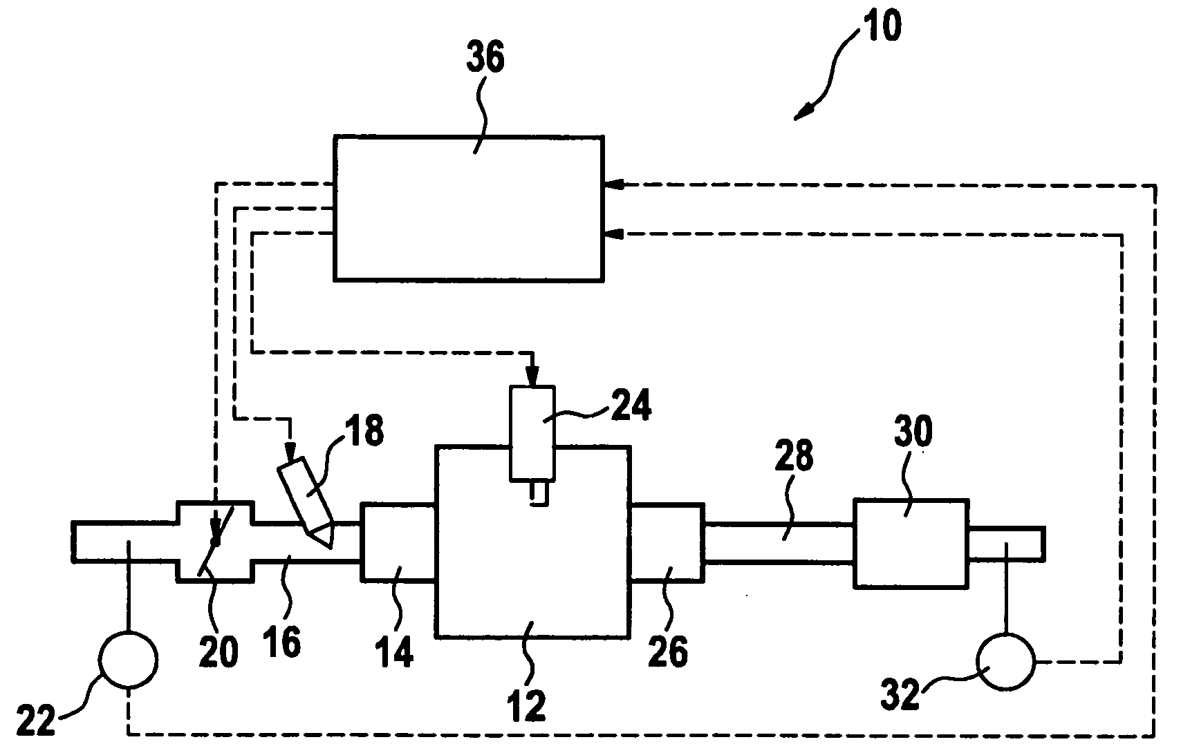
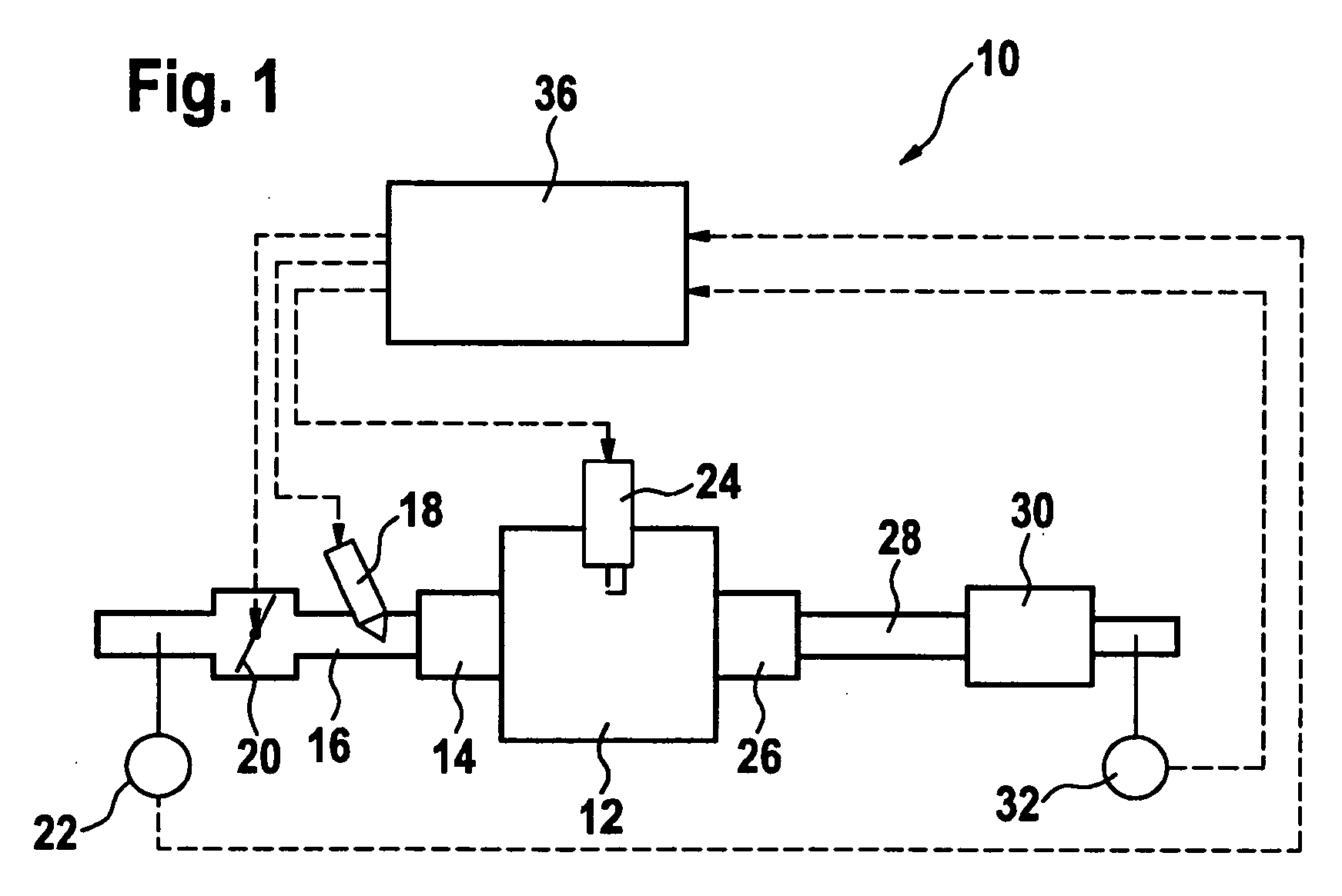
[0021]In FIG. 1, an internal combustion engine is identified as a whole by reference numeral 10. The internal combustion engine includes multiple cylinders having multiple combustion chambers, only one of which, however, is shown in FIG. 1, identified by reference numeral 12. Combustion chamber 12 is connectable to an intake manifold 16 via an intake valve 14.

[0022]In the present exemplary embodiment, fuel is injected therein via an injector 18. However, the operating principles and method described below are also applicable to internal combustion engines having direct fuel injection, for example direct gasoline injection. A throttle valve 20 is also situated in intake manifold 16. In the present exemplary embodiment, the air mass flowing in intake manifold 16 is detected by an air mass sensor 22.

[0023]The air / fuel mixture present in combustion chamber 12 is ignited by a spark plug 24. Hot combustion exhaust gases are discharged from combustion chamber 12 to an exhaust pipe 28 via a...


PUM


Abstract

In a method for operating an internal combustion engine, the fuel is supplied to at least one combustion chamber via at least one injector, which method includes the following steps: a) a total injection is divided into a basic injection and at least one measured injection; b) the injection time of the measured injection is successively decreased and the injection time of the basic injection is successively increased so that a total injection quantity ascertained from a valve characteristic curve remains the same.

Description

BACKGROUND OF THE INVENTION[0001]1. Field of the Invention[0002]The present invention relates to a method and a device for operating an internal combustion engine, in which the fuel is supplied to at least one combustion chamber via at least one injector, and in which a characteristic curve of the injector is adjusted.[0003]2. Description of Related Art[0004]Internal combustions engines having gasoline injection into an intake manifold as well as direct gasoline injection into the particular combustion chambers are known. The gasoline is injected by at least one injector. This injector must cover a wide quantity range. As a rule, the range extends from the idle point, or also from a fired overrun, which defines a minimum quantity, to full load at high speeds, which defines a maximum quantity.[0005]The fuel quantity injected by the injector ideally has a linear correlation to the opening time of the injector. However, a very broad linear range means that the cost of manufacturing the...

Claims


Application Information

Patent Timeline
Patent Type & Authority Applications(United States)
IPC IPC(8): F02D41/30
CPCF02D41/1454F02D41/2438Y02T10/44F02D41/402F02D2200/0614F02D41/2467Y02T10/40F02D41/14F02D41/24F02D41/40
Inventor SAMENFINK, WOLFGANGKUFFERATH, ANDREAS
Owner ROBERT BOSCH GMBH
Why Eureka
Try Eureka