Exhaust-gas purification apparatus and method for purifying exhaust gas

a technology of exhaust gas and purification apparatus, which is applied in mechanical equipment, machines/engines, electric control of exhaust, etc., can solve the problems of increased fuel consumption, adverse effect of engine, and increased pressure loss in the exhaust passage, so as to reduce the adverse influence enhance the purification rate of the internal combustion engin

Inactive Publication Date: 2009-12-10
DENSO CORP +1
View PDF9 Cites 27 Cited by
  • Summary
  • Abstract
  • Description
  • Claims
  • Application Information

AI Technical Summary

Benefits of technology

[0005]In view of the foregoing and other problems, it is an object of the present invention to produce an exhaust-gas-purification apparatus for controlling a reducing agent charged to enhance a NOx purification rate of an internal combustion engine and configured to restrict an adverse influence to the internal combustion engine. It is another object of the present invention to produce a method for purifying exhaust gas of the internal combustion engine.
[0006]According to one aspect of the present invention, an exhaust-gas purification apparatus for an exhaust-gas-purification system for an internal combustion engine, the system including a NOx catalyst, which is provided in an exhaust passage of the internal combustion engine for selectively purifying NOx in exhaust gas with a reducing agent, charging means, which is for charging the reducing agent into exhaust gas at an upstream of the NOx catalyst, and pressurizing means, which is for pressurizing the reducing agent and supplying the reducing agent to the charging means, the exhaust-gas purification apparatus comprises obtaining means for detecting or estimating catalyst temperature of the NOx catalyst or temperature i...

Problems solved by technology

However, in JP-A-2007-255343, the shielding member and the distribution member increase pressure loss in the exhaust passage.
The pressure loss in the exhaust passage is regularly caused during an operation of the engine, and consequently the engine is ex...

Method used


Image

  • Exhaust-gas purification apparatus and method for purifying exhaust gas
  • Exhaust-gas purification apparatus and method for purifying exhaust gas
  • Exhaust-gas purification apparatus and method for purifying exhaust gas

Examples


embodiment

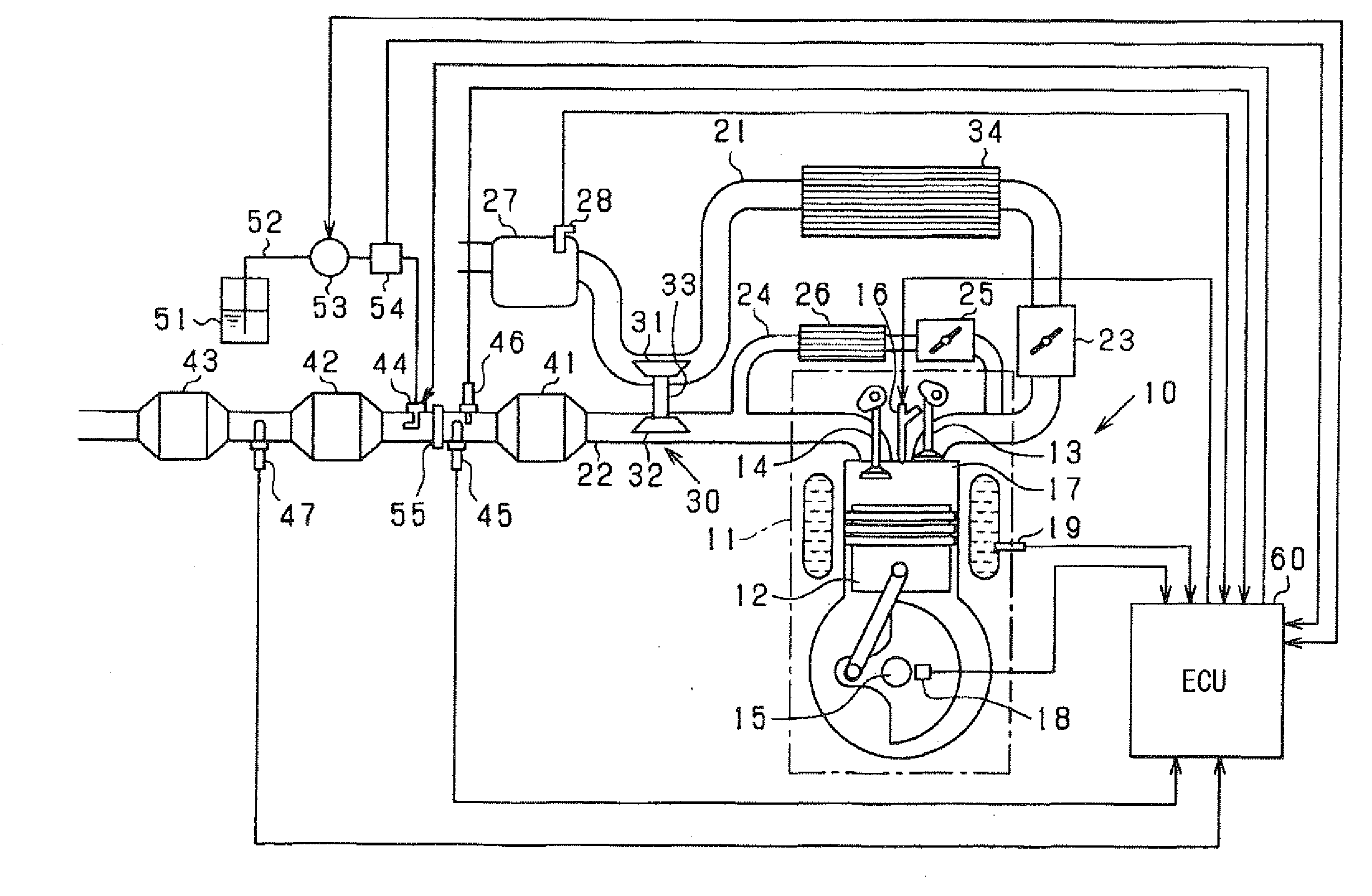
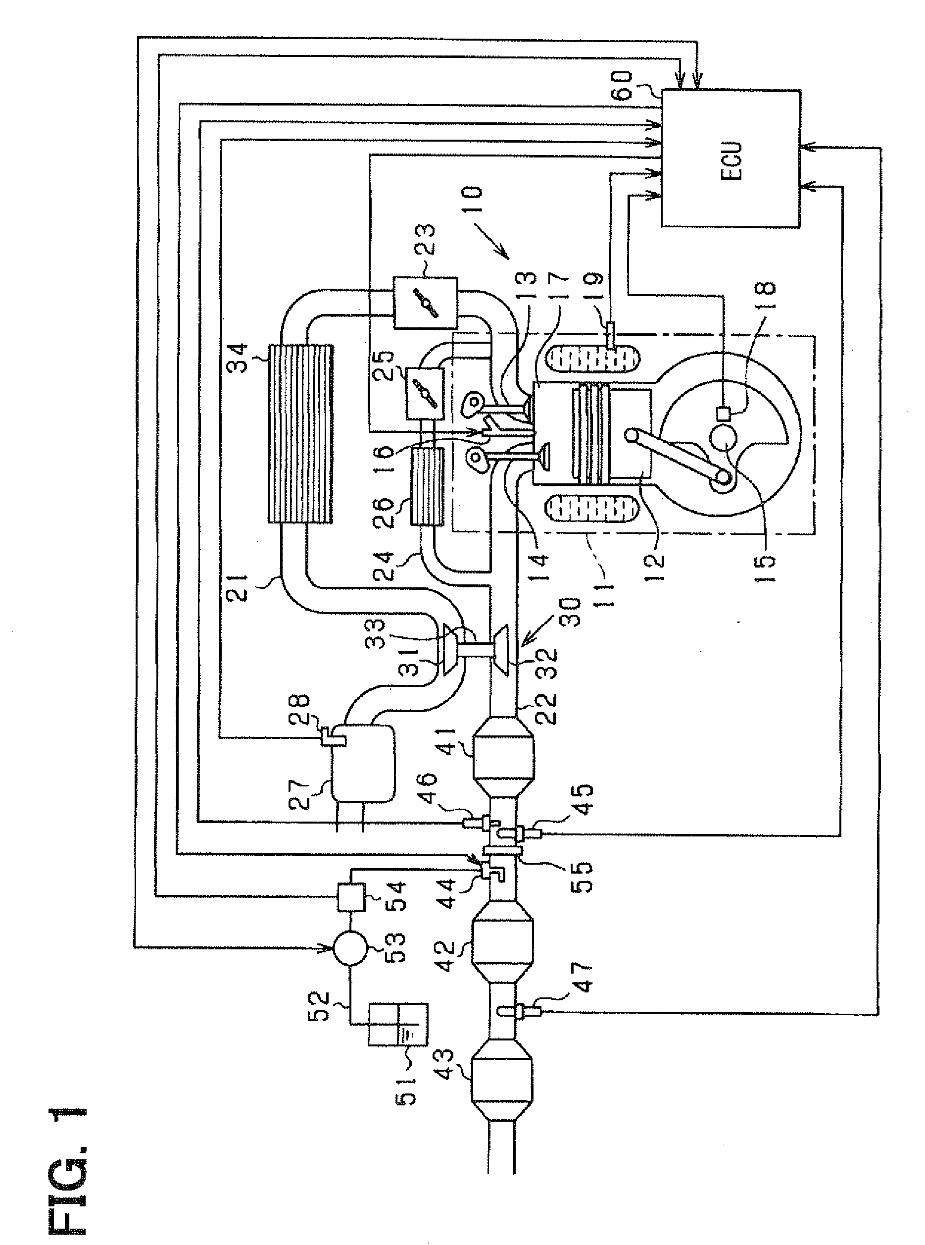
[0015]As follows, an embodiment of the present invention will be described with reference to drawings. In the present embodiment, an engine control system controls a multi-cylinder diesel engine for a vehicle as a controlled object. In the control system, an electronic control unit (ECU) performs various control operations of the engine. In the present embodiment, a common-rail fuel injection system is employed as a fuel injection system, and a urea SCR system is employed as an exhaust-gas-purification system. First, an entire system will be described with reference to FIG. 1. An engine 10 includes an engine main body 11, which has a reciprocating engine structure. A piston 12 is movable back and forth in a cylinder of the engine main body 11. An intake valve 13 and an exhaust valve 14 are respectively and correspondingly provided to an intake port and an exhaust port for opening and closing the intake port and the exhaust port. A crankshaft 15 is rotatable in response to the moveme...


PUM


Abstract

A NOx catalyst is provided in an exhaust passage of an internal combustion engine for selectively purifying NOx in exhaust gas with a reducing agent. A charging unit charges the reducing agent at an upstream of the NOx catalyst. A pressurizing unit supplies the reducing agent to the charging unit. An obtaining unit detects or estimates catalyst temperature of the NOx catalyst or temperature information, which is correlated with the catalyst temperature. A particle size control unit changes reducing-agent pressure of reducing agent, which is pressurized by the pressurizing unit and supplied to the charging unit, to control an atomized particle size of the reducing agent, which is atomized from the charging unit and charged into exhaust gas, based on the catalyst temperature or the temperature information.

Description

CROSS REFERENCE TO RELATED APPLICATIONS[0001]This application is based on and incorporates herein by reference Japanese Patent Application No. 2008-147854 filed on Jun. 5, 2008.FIELD OF THE INVENTION[0002]The present invention relates to an exhaust-gas purification apparatus for an exhaust gas purification system such as a selective catalytic reduction (SCR) system having a selective reduction catalyst for selectively purifying nitrogen oxide (NOx) in exhaust gas of an internal combustion engine by charging ammonia as a reducing agent. The present SCR system generally employs a urea aqueous solution as a reducing agent, and such an SCR system is known as a urea SCR system. The present invention relates to a method for purifying exhaust gas of the internal combustion engine.BACKGROUND OF THE INVENTION[0003]In recent years, development of a urea SCR system is in progress and partially in practical use. Such a urea SCR system is employed as an exhaust-gas-purification system for an eng...

Claims


Application Information

Patent Timeline
IPC IPC(8): F01N9/00F01N3/10F01N3/00
CPCF01N3/208F01N2610/02Y02T10/24F01N2900/1602F01N2900/0408Y02T10/12
Inventor FUJITA, TATSUYAMARUYAMA, MASATOSHI
Owner DENSO CORP
Why Eureka
Try Eureka