
Exhaust purification device for internal combustion engine

a technology of exhaust gas purification device and internal combustion engine, which is applied in the direction of machines/engines, instruments, heat measurement, etc., can solve the problems of deteriorating the nox purification ra

Active Publication Date: 2017-09-12
ISUZU MOTORS LTD
View PDF5 Cites 2 Cited by
  • Summary
  • Abstract
  • Description
  • Claims
  • Application Information

AI Technical Summary

Benefits of technology

The present invention relates to an exhaust gas purification device for internal combustion engines. The device includes a filter, a urea water spraying unit, a selective reduction catalyst and an electrostatic capacity detecting unit. The device can detect the temperature of the filter and estimate the inside temperature of the filter based on the detected electrostatic capacity. The device can carry out forced regeneration by supplying fuel to the filter and raising the temperature of the filter to or over burning temperature of the particulate matter. This allows the device to effectively improve the NOx purification rate by raising the temperature of the exhaust gas flowing into the SCR to the activation temperature at an early stage.

Problems solved by technology

This can be a cause of deteriorating the NOx purification rate.

Method used


Image

  • Exhaust purification device for internal combustion engine
  • Exhaust purification device for internal combustion engine
  • Exhaust purification device for internal combustion engine

Examples


Embodiment Construction

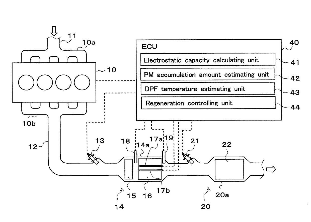
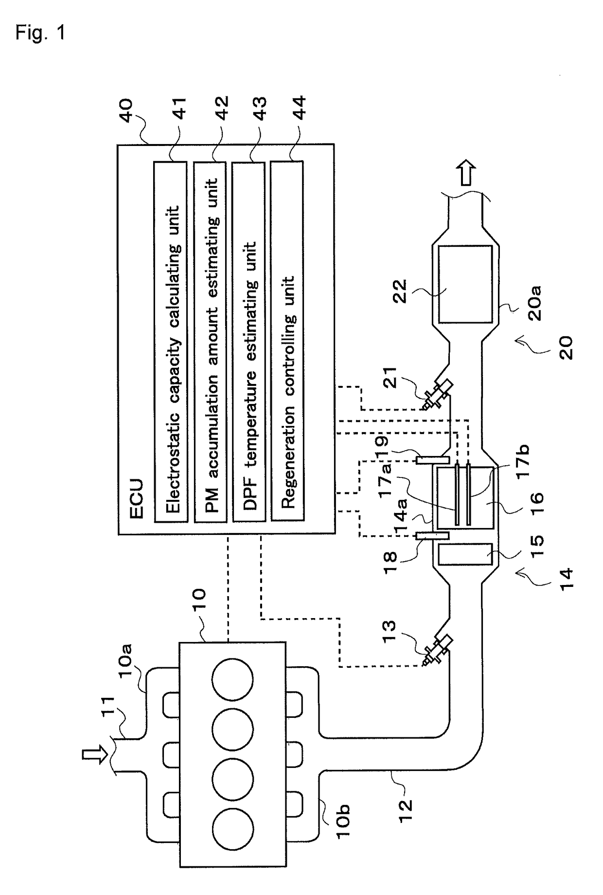
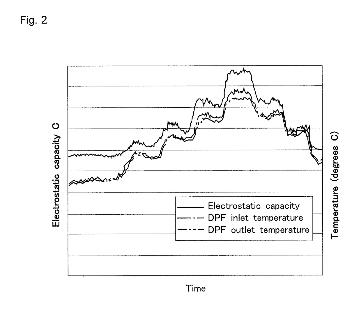
[0019]Hereinafter, with reference to FIGS. 1 to 3, an exhaust gas purification device of an internal combustion engine according to embodiments of the present invention will be described. Identical parts are given identical reference numerals and symbols, and their names and functions are identical as well. Therefore, detailed description of such parts will not be repeated.

[0020]As illustrated in FIG. 1, a diesel engine (hereinafter, simply referred to as “engine”) 10 has an intake manifold 10a and an exhaust manifold 10b. An intake passage 11 for introducing fresh air is connected to the intake manifold 10a, and an exhaust passage 12 for discharging an exhaust gas to the atmosphere is connected to the exhaust manifold 10b. A pre-stage (upstream) post-treatment device 14 and a post-stage (downstream) post-treatment device 20 are provided in the exhaust passage 12. The post-treatment device 14 is arranged upstream of the post-treatment device 20. It should be noted that the engine 10...


PUM


Abstract

An exhaust gas purification device includes a diesel particulate filter (DPF) for capturing particulate matter (PM) in an exhaust gas, a selective catalytic reduction (SCR) device for reducing NOx in the exhaust gas, detecting units for detecting the DPF electrostatic capacity, an estimating unit for estimating the inside temperature of the DPF based on the electrostatic capacity, and a controlling unit for executing forced DPF regeneration. A lower limit temperature is defined as a temperature to trigger PM combustion, and an upper limit temperature is defined as a temperature to avoid filter erosion. The controlling unit executes the forced regeneration with an amount of fuel supplied for causing the inside temperature to reach the lower limit temperature, when the inside temperature is at or above the SCR activation temperature, and executes the forced regeneration with another amount of fuel supplied for causing the inside temperature to reach the upper limit temperature, when the inside temperature is below the SCR activation temperature.

Description

CROSS-REFERENCE TO RELATED APPLICATIONS[0001]This application is a U.S. National Stage Application, which claims the benefit under 35 U.S.C. §371 of PCT International Patent Application No. PCT / JP2014 / 053738, filed Feb. 18, 2014, which claims the foreign priority benefit under 35 U.S.C. §119 of Japanese Patent Application No. 2013-039064, filed Feb. 28, 2013, the contents of which are incorporated herein by reference.TECHNICAL FIELD[0002]The present invention relates to an exhaust gas purification device of an internal combustion engine.BACKGROUND ART[0003]A diesel particulate filter (hereinafter referred to as “DPF”), for example, is known as a filter for collecting particulate matter (hereinafter referred to as “PM”) in an exhaust gas emitted from a diesel engine.[0004]The DPF has a limitation on an amount of collecting PM. Thus, it is necessary to carry out forced regeneration that periodically burns and removes the accumulated PM. The forced regeneration is performed by supplyin...

Claims


Application Information

Patent Timeline
Patent Type & Authority Patents(United States)
IPC IPC(8): F01N3/025F01N3/20F01N13/00F01N3/035F01N9/00
CPCF01N3/0253F01N3/035F01N3/2066F01N9/002F01N13/009F01N2240/04F01N2560/12F01N2570/14F01N2610/02F01N2610/03F01N2900/0601F01N2900/1602F01N2900/1626G01K2205/04Y02T10/24Y02T10/47Y02T10/12Y02T10/40
Inventor UCHIYAMA, TADASHIASO, MITSUHIRONODA, MASAFUMI
Owner ISUZU MOTORS LTD
Learn More