Insulation for pipe-in-pipe systems

a technology of insulation and pipe-in-pipe system, which is applied in the direction of thermal insulation, rigid pipes, flexible pipes, etc., can solve the problems of wet coated pipelines that are often less attractive in deep water, relatively heavy and expensive pip systems, and high cost of materials. achieve the effect of substantial cost advantag

Inactive Publication Date: 2009-12-10
HEEREMA MARINE CONTRACTORS NEDERLAND
View PDF0 Cites 24 Cited by
  • Summary
  • Abstract
  • Description
  • Claims
  • Application Information

AI Technical Summary

Benefits of technology

[0062]Pre-assembled pipe sections according to the present invention may be assembled into a Pipe-in-pipe pipeline very quickly, leading to a substantial cost advantage.

Problems solved by technology

However, wet coated pipelines are often less attractive in deep water since there are only a few materials that can resist water pressure at depths over 1,000 meters.
These materials are generally very costly.
U.S. Pat. No. 6,179,523 B1 is a system with a relatively wide outer pipe and thus a relatively heavy and expensive PiP system.
This system is unsuitable for the present needs in the field of marine pipeline laying.
As mentioned, wet coated pipelines are disadvantageous in many situations, in particular in deep water.
This system is therefore also unsuitable for the present needs in the field of marine pipeline laying.
Pipe-in-pipe systems are especially heavy since the weight of two pipes needs to be supported by a single installation vessel, e.g. a J-lay vessel or an S-lay vessel.
This method is unsuitable for marine pipe-laying, because the thin walled outer pipe is not strong enough to be used in pipelay such as J-lay.
The solution of helically winding a thin outer pipe thus is unsuitable for the present needs in the field of marine pipeline laying.

Method used


Image

  • Insulation for pipe-in-pipe systems
  • Insulation for pipe-in-pipe systems
  • Insulation for pipe-in-pipe systems

Examples


Embodiment Construction

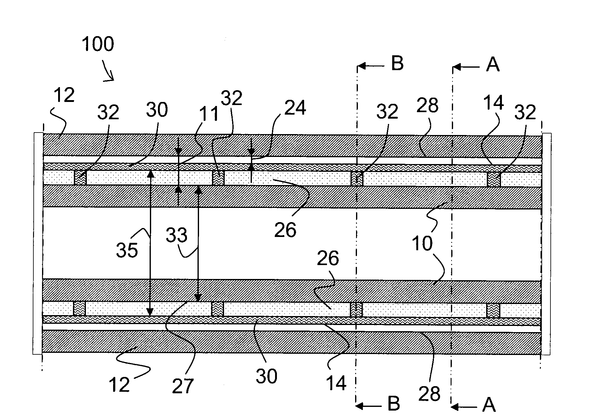
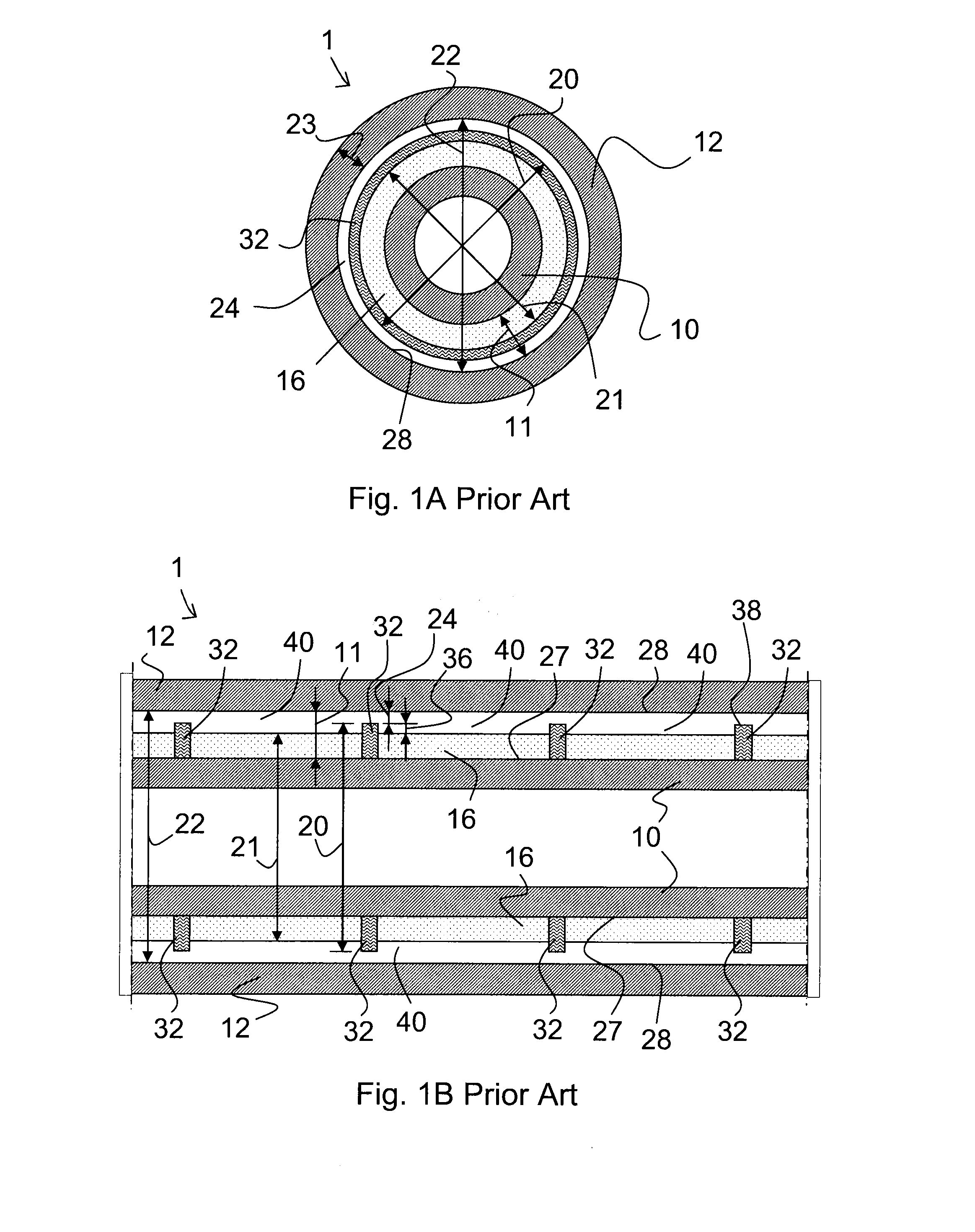
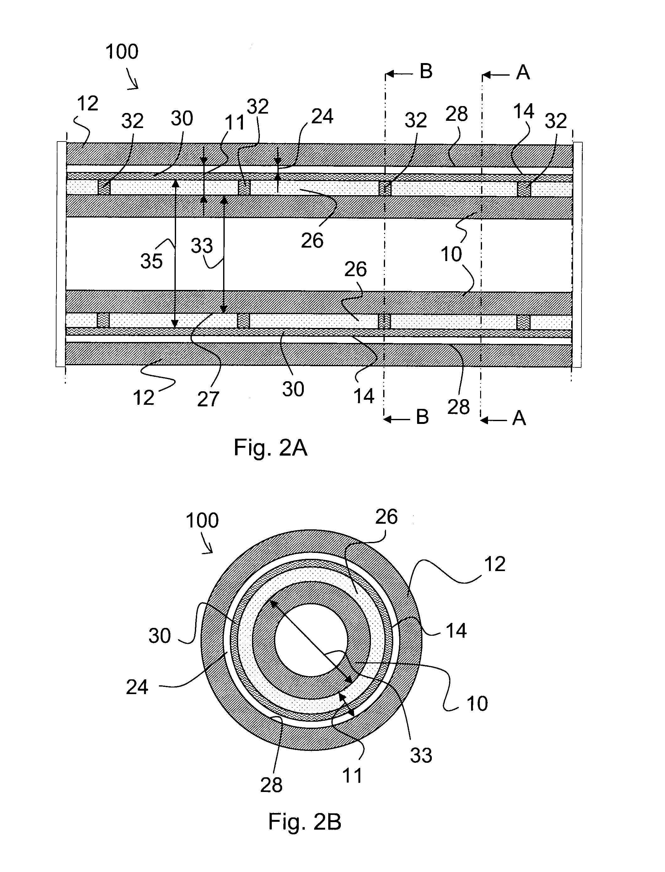
[0071]FIGS. 1A and 1B show a pipe-in-pipe assembly 1 of the prior art, i.e. according to U.S. Pat. No. 6,179,523 B1. An inner pipe 10 is provided having an inner diameter and outer diameter and a wall thickness. A thick walled outer pipe 12 is provided around the inner pipe 10. The outer pipe 12 has an inner diameter 22 and an outer diameter and a wall thickness 23. An insulation layer 16 is provided around the inner pipe 10 for thermal insulation. An annulus 11 is defined as the area between the outer wall 27 of the inner pipe and the inner wall 28 of the outer pipe 12.

[0072]Centralizers 32 are provided at regular intervals. The centralizers 32 have an outer diameter 20 which is greater than the outer diameter 21 of the insulation layer 16. The centralizers 32 thus project outwardly from the insulation layer 16 over a distance 36, thereby preventing the insulation layer 16 from coming into contact with the inner wall 28 of the outer pipe 12.

[0073]Due to the larger diameter 20 of th...


PUM

PropertyMeasurementUnit
depthsaaaaaaaaaa
sizeaaaaaaaaaa
densityaaaaaaaaaa

Abstract

A method of providing an insulated pipe-in-pipe assembly includes providing an inner pipe; providing a thermal insulation layer of a highly porous solid formed from a gel, the highly porous solid having pores smaller than 100 nanometre, the thermal insulation layer being provided around the inner pipe for thermal insulation of the inner pipe; providing a protective layer on the outer surface of the thermal insulation layer for protecting the thermal insulation layer, and providing a thick walled outer pipe around the protective layer. A Pipe-in-pipe assembly and a pipe-in-pipe section made by the method are also provided.

Description

CROSS-REFERENCE TO RELATED APPLICATIONS[0001]This application claims the benefit of U.S. Provisional Application No. 61 / 012,639, filed Dec. 10, 2007, the contents of which is incorporated by reference herein.FIELD OF THE INVENTION[0002]The field of the invention relates to pipelines, more specifically to insulation of subsea pipelines, more specifically insulation of subsea pipe-in-pipe systems.PRIOR ART[0003]Pipe-in-pipe systems (PiP systems) are known in the oil and gas industry. In subsea environments, PiP systems can be used to provide pipelines with good thermal insulation. The insulation material is generally provided in the annulus between the inner and outer pipe to improve the thermal performance of the PiP system. Since the outer pipe will resist the water pressure, no pressure is exerted on the insulation material and consequently, conventional insulation materials can be used.[0004]In particular in deep to ultra deep water, PiP systems are frequently used. PiP systems ha...

Claims


Application Information

Patent Timeline
Patent Type & Authority Applications(United States)
IPC IPC(8): F16L59/00
CPCF16L9/18F16L59/143F16L59/123
Inventor VAN OOSTEN, JEROEN
Owner HEEREMA MARINE CONTRACTORS NEDERLAND
Why Eureka
Try Eureka