Double fed synchronous generator motor

a synchronous generator and synchronous technology, applied in the direction of electric generator control, machine/engine, dynamo-electric converter control, etc., can solve the problems of missing the opportunity to increase the afc amount and enhance the efficiency at a low area of the water turbine output, so as to achieve the effect of improving efficiency

Active Publication Date: 2009-12-10
HITACHI MITSUBISHI HYDRO
View PDF4 Cites 15 Cited by
  • Summary
  • Abstract
  • Description
  • Claims
  • Application Information

AI Technical Summary

Benefits of technology

[0016]The present invention has been implemented in view of the foregoing challenge, and has an object to provide a double fed synchronous generator motor which is used for a variable speed pumped-storage power generating system and in which a variable speed width in a low rotating speed area in a power generating operation is increased, whereby the operation can be performed with an enhanced efficiency.

Problems solved by technology

However, the rotating speed is restricted by the lower limit of the variable speed width, and thus in many cases the reversible pump-turbine is operated while the speed is fixed to the lower limit speed of the variable speed width.
Accordingly, the operation at a fixed variable speed width over the whole area of the water turbine output of the reversible pump-turbine means that an opportunity of enhancing the efficiency at a low area of the water turbine output is missed and also an opportunity of increasing the AFC amount is missed in the case of the pumping operation.
In other words, there is a challenge of enhancing the power generation efficiency in the low rotating speed area and the pumping AFC amount in the water turbine operation or in the pumping operation in the variable speed pumped-storage power generating system based on the double fed synchronous generator motor.

Method used


Image

  • Double fed synchronous generator motor
  • Double fed synchronous generator motor
  • Double fed synchronous generator motor

Examples


first embodiment

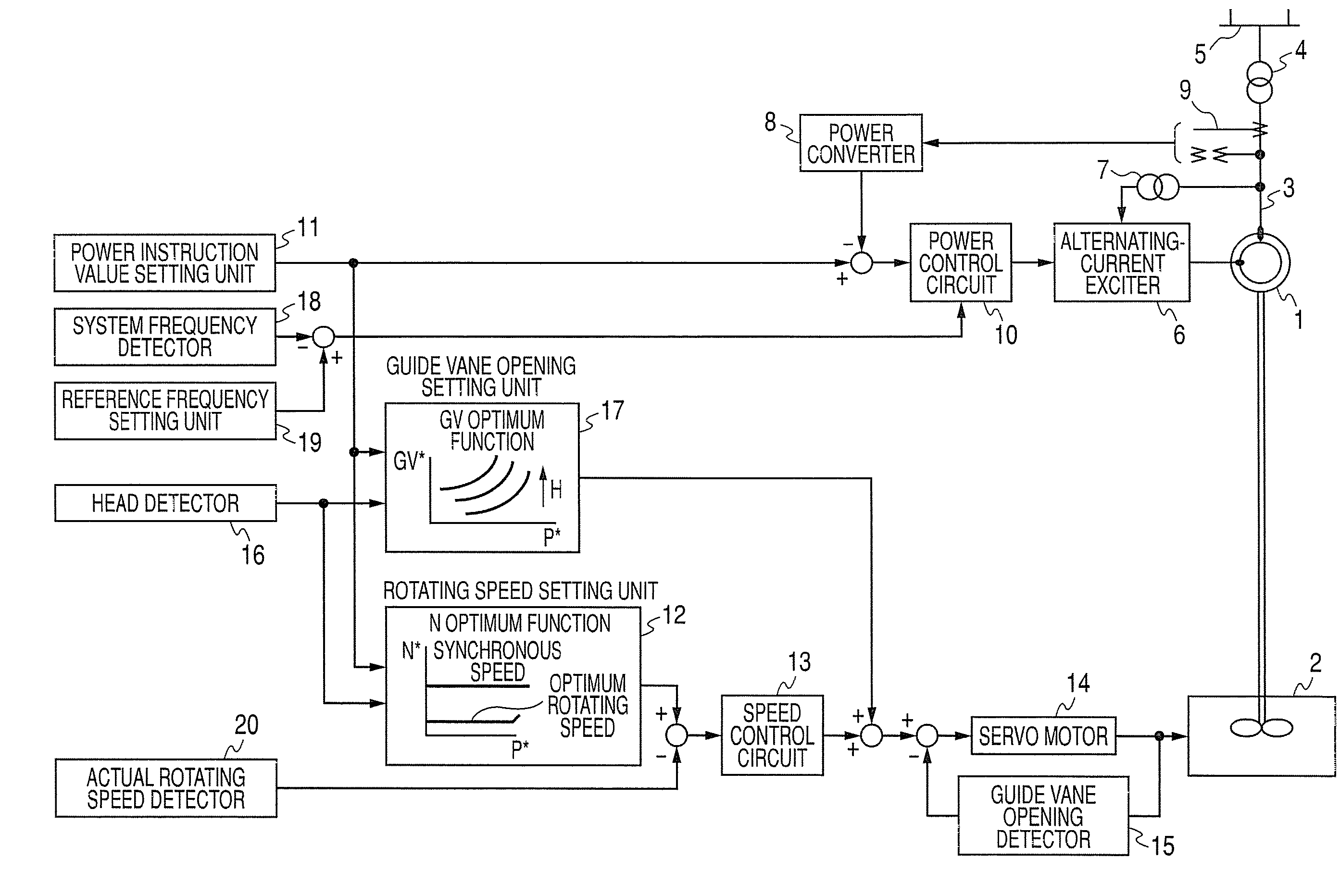
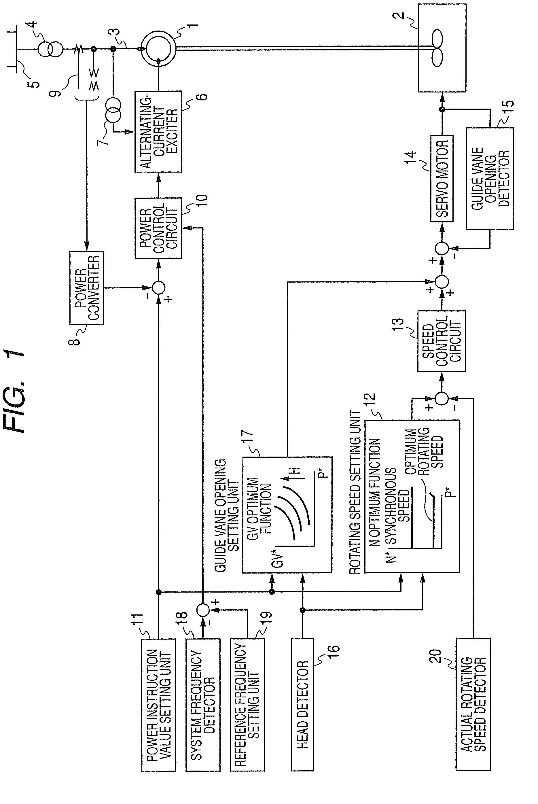
[0041]A first embodiment according to the present invention will be described with reference to FIG. 1.

[0042]In FIG. 1, the rotor of a double fed synchronous generator motor 1 is driven by a reversible pump-turbine 2, and the winding of the stator of the double fed synchronous generator motor 1 is connected to an electric power system 5 through a generator bus bar 3 and a main transformer 4. An alternating-current (AC) exciting device 6 is supplied with power from the generator bus bar 3 through an exciting transformer 7, and supplies the winding of the rotor of the double fed synchronous generator motor 1 with AC exciting current having the frequency corresponding to the difference between the system frequency and the rotating speed. A power converter 8 detects the output of the double fed synchronous generator motor 1 from a secondary-side signal of a current & voltage transformer 9 connected to the generator bus bar 3. A power control circuit 10 generates such a control signal th...

second embodiment

[0062]In the first embodiment, the optimum rotating speed is set on the basis of the power instruction value, and this is based on the assumption that the double fed synchronous generator motor 1 feeds rated reactive power by large excitation current.

[0063]In the second embodiment, a reactive power detector 21 is provided as shown in FIG. 3, and the exciting current may be small when the reactive power by large excitation current is equal to a small value below the rated power. Accordingly, the second embodiment provides a control system of correcting the variable speed width so that the variable speed width is further enlarged by the amount corresponding to the reduction of the exciting current and enhancing the power generation efficiency under a partial load.

[0064]FIG. 4 shows an example of the operation. The new optimum rotating speed “N=15×Pref (Pu)+561 (rpm)” described in the first embodiment is corrected by using actual reactive power by large excitation current Qact (mvar) a...

third embodiment

[0067]In the first embodiment, the optimum rotating speed is set on the basis of the power instruction value, and it is based on the assumption that the double fed synchronous generator motor 1 feeds power at the rated lagging power factor.

[0068]In the third embodiment, a lagging power factor detector 22 is provided as shown in FIG. 5, and the exciting current may be small when the lagging power factor is near to 1. Accordingly, the third embodiment provides a control system of correcting the variable speed width so that the variable speed width is further enlarged by the amount corresponding to the reduction of the exciting current and enhancing the power generation efficiency under a partial load.

[0069]FIG. 6 shows an example of the operation. The new optimum rotating speed “N=15×Pref(Pu)+561 (rpm)” described in the first embodiment is corrected by using an actual lagging power factor Pfact(%) and a rated lagging power factor Pfrate(%), thereby determining the new optimum rotating...


PUM


Abstract

A double fed synchronous generator motor which is coupled to a reversible pump-turbine and operated while switched to a power generating operation mode or a pumping operation mode, is equipped with a controller for controlling the double fed synchronous generator motor so that power output from the double fed synchronous generator motor is coincident with an instruction value and the rotating speed is set between upper and lower limit values of the rotating speed by changing exciting current. In the power generating operation mode, the lower limit value of the rotating speed is varied by active power output from the double fed synchronous generator motor, and when the active power is small, the lower limit value of the rotating speed is set to a smaller value than that when the active power is large.

Description

BACKGROUND OF THE INVENTION[0001]1. Field of the Invention[0002]The present invention relates to a double fed synchronous generator motor which is connected to an electric power system at a stator side and to a frequency-variable power converter at a rotor side, coupled to a reversible pump-turbine and operated while switched to an electric power generating operation mode or a pump-up operation mode.[0003]2. Description of the Related Art[0004]A double fed synchronous generator motor can be generally operated at fixed upper and lower speeds with the synchronous speed at the center, that is, within the range of a variable speed width. Furthermore, as disclosed in JP-A-61-240829 (page 4, FIGS. 2 to 5), optimum variable speed widths are set to a pumping operation and a power generating operation respectively in a variable speed pumped-storage power generating system using a double fed synchronous generator motor. The variable speed width is fixed to a value set for any power generation...

Claims


Application Information

Patent Timeline
Patent Type & Authority Applications(United States)
IPC IPC(8): F03B13/08H02P9/48H02P9/04
CPCH02P9/007H02P2101/10H02P2207/05H02P23/03
Inventor KENZAKI, AKIRAMACHINO, TAKESHI
Owner HITACHI MITSUBISHI HYDRO
Why Eureka
Try Eureka