Atomic beam tube with counter optical or atomic beams

Inactive Publication Date: 2009-12-10
SEPA SISTEMI ELETTRONICI PER AUTOMAZIONE +1
View PDF1 Cites 21 Cited by
  • Summary
  • Abstract
  • Description
  • Claims
  • Application Information

AI Technical Summary

Problems solved by technology

As far as it is known, such optical beam tube standards are either of the

Method used


Image

  • Atomic beam tube with counter optical or atomic beams
  • Atomic beam tube with counter optical or atomic beams
  • Atomic beam tube with counter optical or atomic beams

Examples


Embodiment Construction

[0027]1. Counter Propagating Optical Beams, Single One-Way Atomic Beam

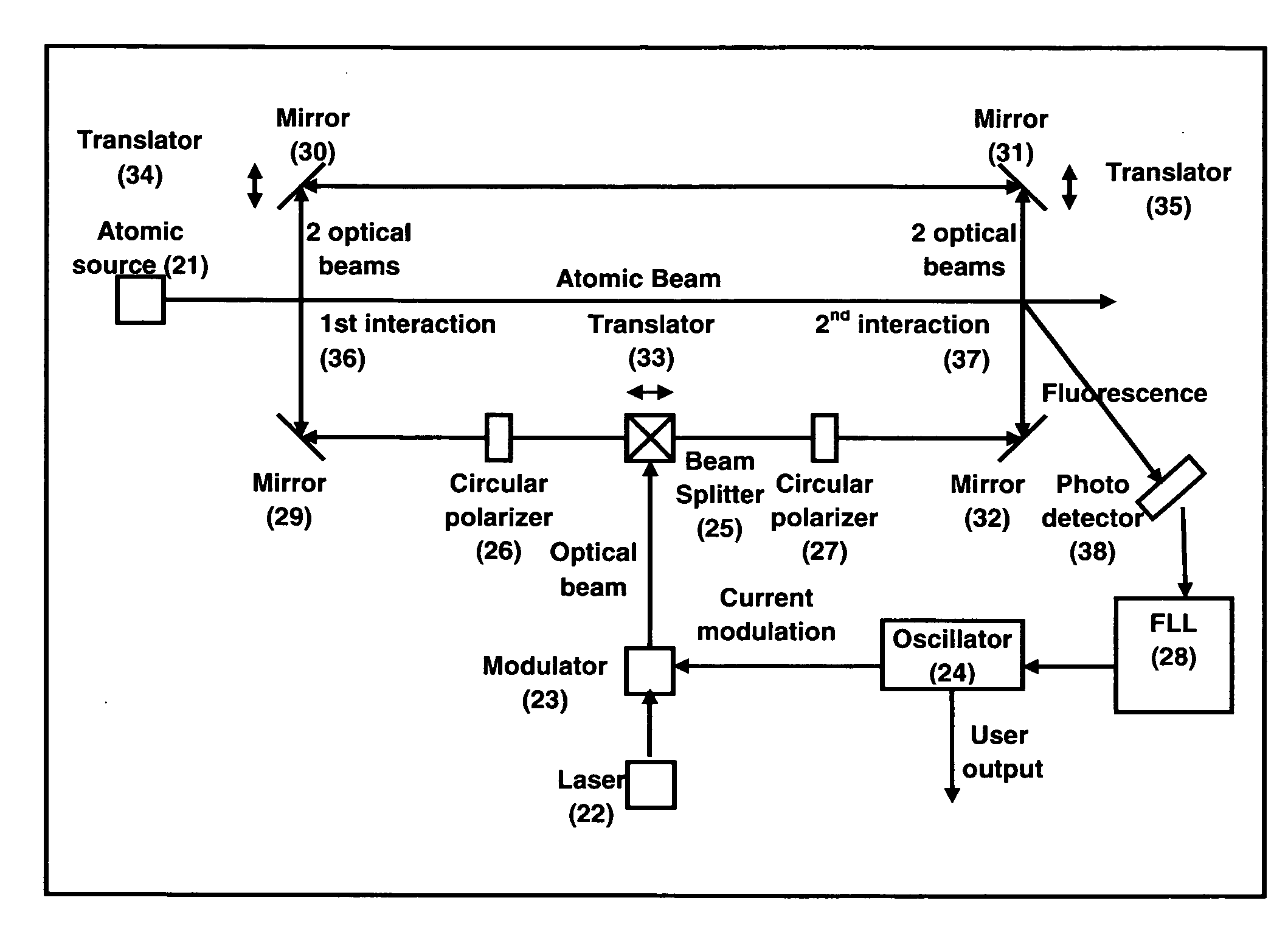
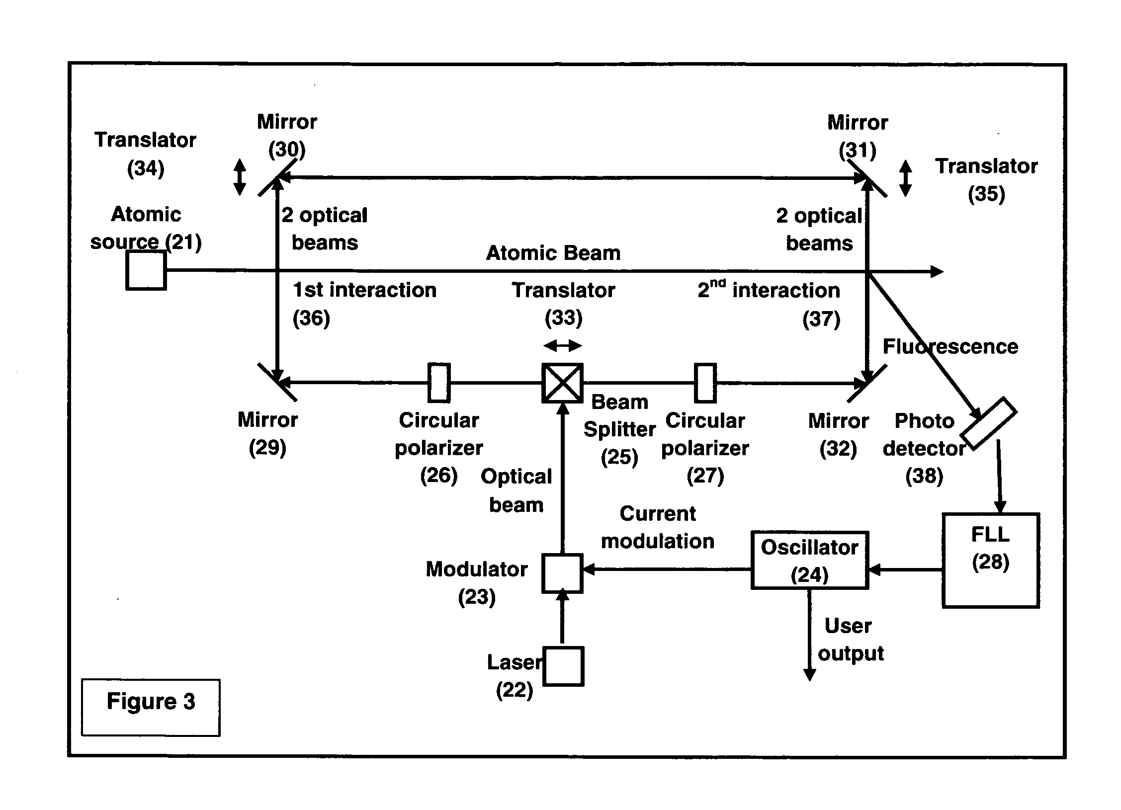
[0028]In this configuration a round optical beam configuration is employed, such as shown in FIG. 3. An atomic source (21) generates a collimated atomic beam inside a vacuum envelope (not shown in the figure). A laser (22) emits optical beam at a wavelength which corresponds to the D1 or the D2 transition of the used alkali atom (for Cs D1 wavelength is 894.35 nm and D2 wavelength is 852.11 nm). The optical beam is modulated by a modulator (23) at a frequency around half the hyperfine transition frequency of the used alkali atom. The said modulation generates two sidebands separated by the hyperfine 0-0 transition frequency (for Cs the hyperfine frequency is around 9.2 GHz). The modulation frequency is generated by an Oscillator (24). The optical beam is then split into two symmetrical left and right beams by a beam splitter (25). Each beam is transmitted through a circular polarizer (a quarter-lambda plate). The ...


PUM


Abstract

An atomic beam tube for frequency standard which employs either counter propagating optical beams or counter propagating atomic beams and Coherent Population Trapping (CPT) is disclosed. Atoms selected from the group consisting of the alkali metal family (Cesium, Rubidium, Potassium, Sodium and Lithium) are emitted from one or two sources to form a single or double atomic beams. The atoms interact with the optical beams at two crossing points. The optical beams are generated by a laser and are modulated at half the hyperfine frequency. The optical beam is splitted into two counter propagating beams in round paths which interact with the atomic beam at two interaction regions. The interaction with the light causes the atoms to enter a CPT state. A dark line in the fluorescence at the second crossing is used to lock an RF oscillator to the atomic hyperfine transition.

Description

FIELD OF THE INVENTION [0001]The present invention relates generally to atomic standards and a method of providing a frequency and / or time based on an atomic standard, and more particularly to atomic frequency and / or time standards and methods employing a beam tube.STATE OF THE PRIOR ART [0002]The following is a list of prior publications generally related to the field of the present invention:[0003]1. J. Vanier and C. Audoin, The Quantum Physics of Atomic Frequency Standards (Institute of Physics Publishing, Bristol, UK, 1989)[0004]2. R. Lutwak, D. Emmons, R. M. Garvey, and P. Vlitas, Opticaly-Pumped Cesium Beam Frequency Standard for GPS-III, Proceedings of the 33rd Annual Precise Time and Time Interval Systems Applications Meeting Long Beach, Calif. Nov. 27-29, 2001[0005]3. I. Pascaru, Atomic frequency standard using optical pumping for state preparation and magnetic state selection of atoms, U.S. Pat. No. 5,107,226[0006]4. J. Vanier, Atomic clocks based on coherent population tr...

Claims


Application Information

Patent Timeline
IPC IPC(8): H03B17/00
CPCH03L7/26G04F5/145
Inventor LEVI, FILIPPOSTERN, AVINOAM
Owner SEPA SISTEMI ELETTRONICI PER AUTOMAZIONE
Why Eureka
Try Eureka