Digitally controlled oscillator and phase locked loop circuit using the digitally controlled oscillator

Inactive Publication Date: 2009-12-10
KK TOSHIBA
View PDF7 Cites 52 Cited by
  • Summary
  • Abstract
  • Description
  • Claims
  • Application Information

AI Technical Summary

Benefits of technology

[0009]According to an aspect of the invention, there is provided a digitally controlled oscillator comprising: a differential inductor including a positive terminal which outputs a positive-phase oscillation signal, a negative terminal which outputs a negative-phase oscillation signal, and a center tap, and including a first contact point in an arbitrary position between the positive terminal and the center tap, and a second contact point in a position corresponding to the first contact point between the negative terminal and the center tap; a first variab

Problems solved by technology

The greater the quantization noise, the gap between the oscillation frequency and a desired frequency increases, and the carrier to noise ratio (CNR) is deteriorated.
In the DCO disclosed in Related Art 1, however, since the connection positions of the variab

Method used


Image

  • Digitally controlled oscillator and phase locked loop circuit using the digitally controlled oscillator
  • Digitally controlled oscillator and phase locked loop circuit using the digitally controlled oscillator
  • Digitally controlled oscillator and phase locked loop circuit using the digitally controlled oscillator

Examples


first embodiment

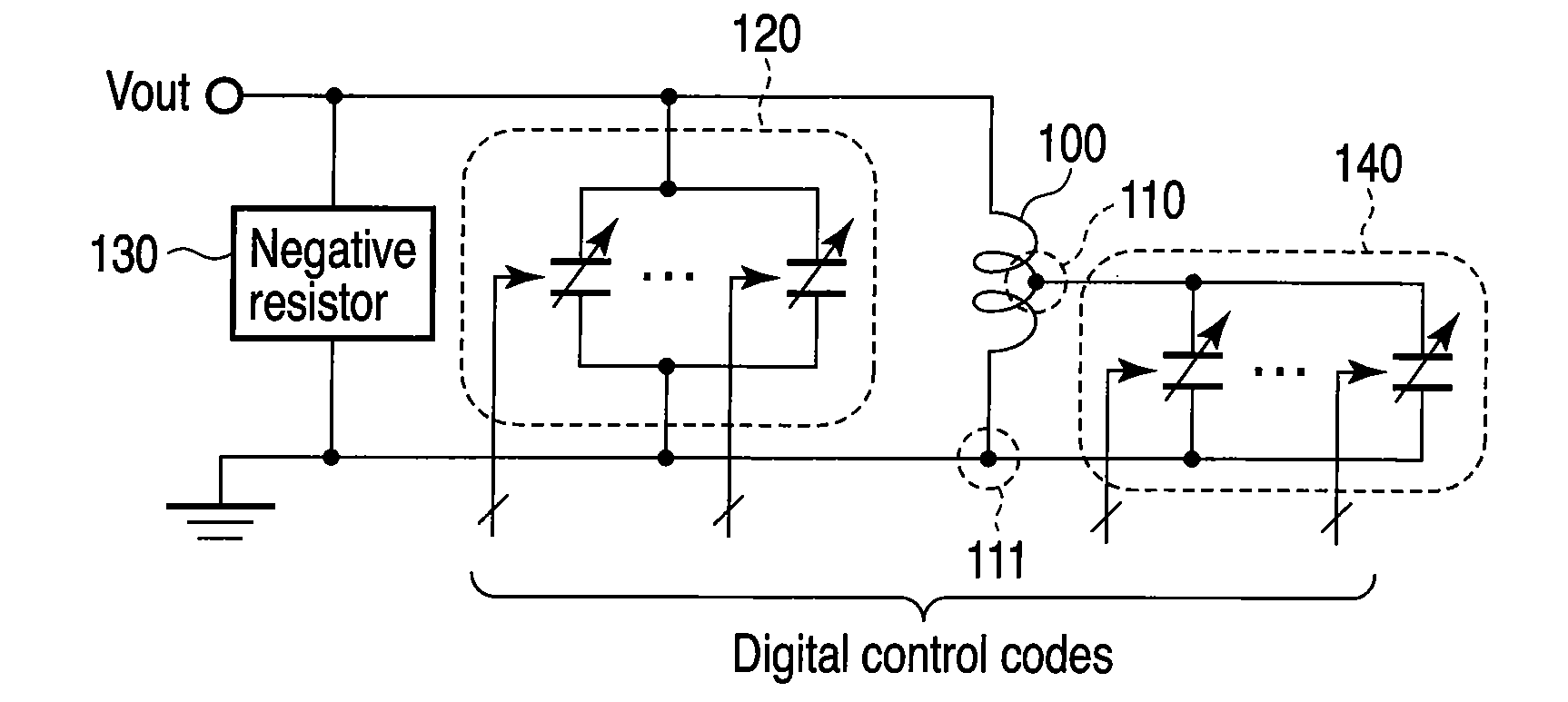
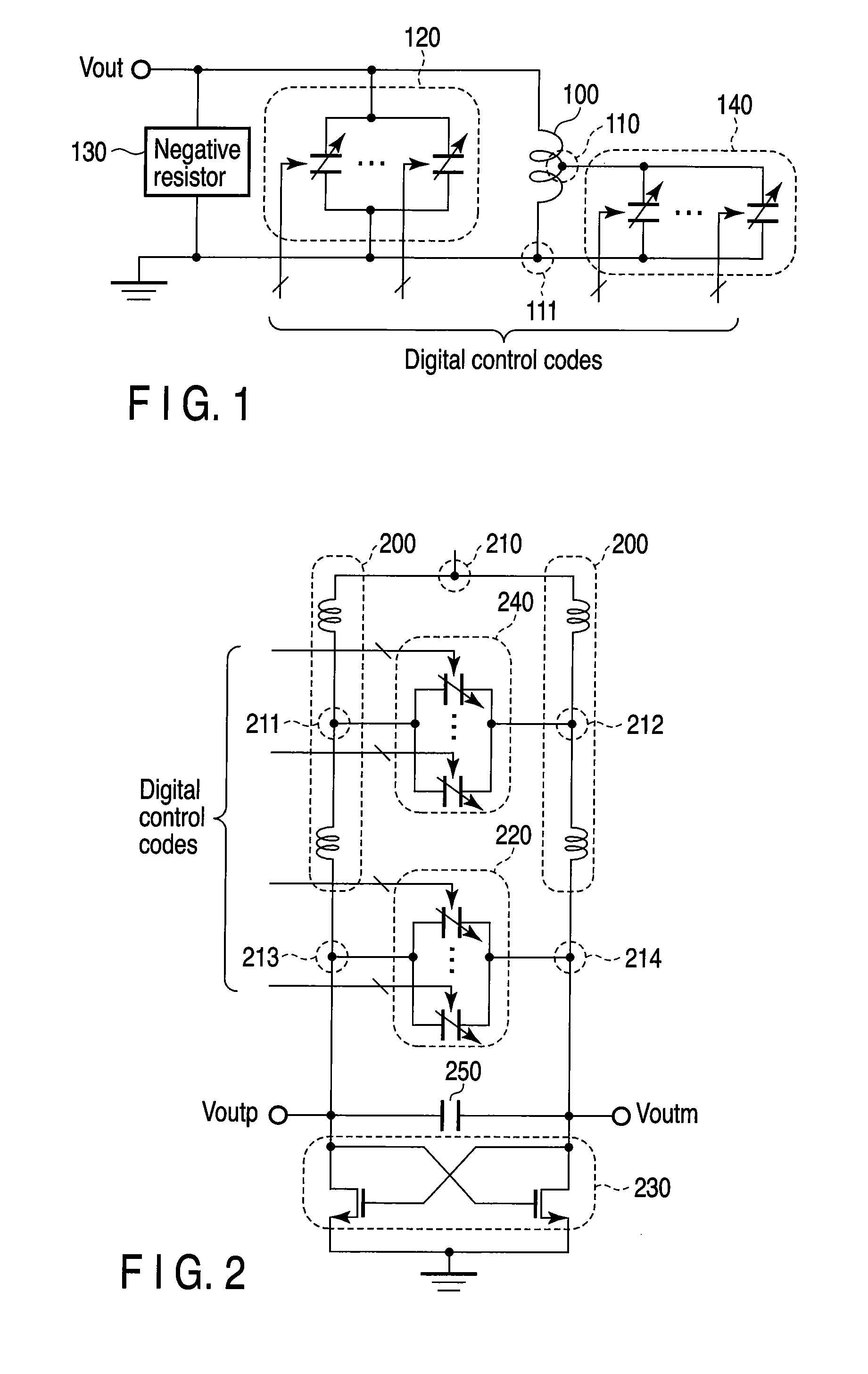
[0027]As shown in FIG. 1, a digitally controlled oscillator according to a first embodiment of the present invention includes an inductor 100, a coarse tuning variable capacitor bank 120, a negative resistor 130, and a fine tuning variable capacitor bank 140.

[0028]One end of the inductor 100 is connected to an output terminal Vout and the other end 111 is grounded. One end of the coarse tuning variable capacitor bank 120 and one end of the negative resistor 130 are commonly connected to the one end of the inductor 100. The inductor 100 has a contact point 110 between the one end and the other end 111, and one end of the fine tuning capacitor bank 140 is connected to the contact point 110. The other end of the coarse tuning variable capacitor bank 120, the other end of the negative resistor 130, and the other end of the fine tuning variable capacitor bank 140 are commonly connected to the other end 111 of the inductor 100.

[0029]The coarse tuning variable capacitor bank 120 is provide...

second embodiment

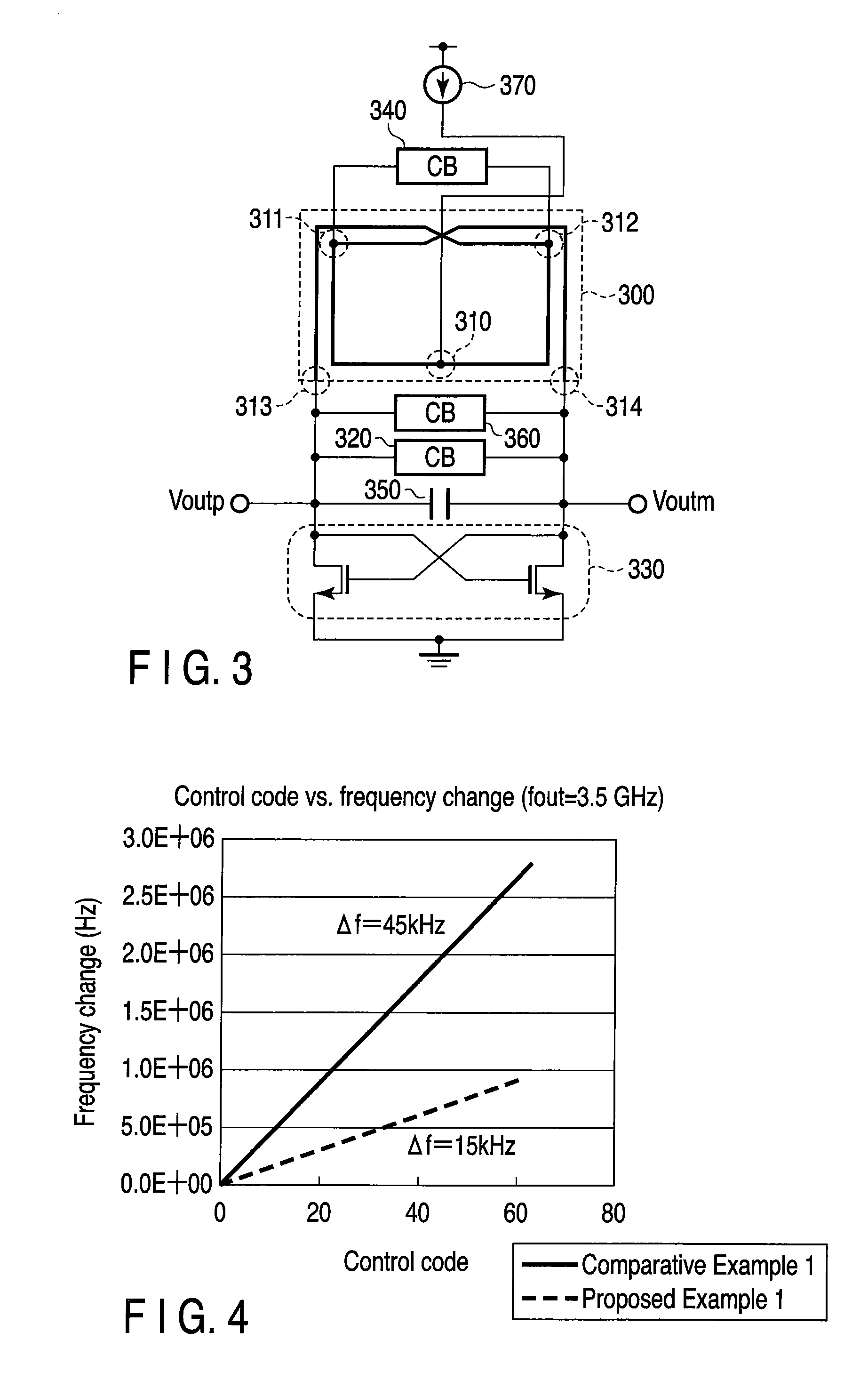
[0060]As shown in FIG. 5, in a digitally controlled oscillator according to a second embodiment of the present invention, the differential inductor 300 and the fine tuning variable capacitor bank 340 in the above-described digitally controlled oscillator shown in FIG. 3 are replaced with a differential inductor 400 and a fine tuning variable capacitor bank 440, respectively. In the descriptions that follow, the same components of FIG. 5 as those of FIG. 3 will be denoted by the same reference numerals and different components will be mostly discussed.

[0061]The number of turns of the differential inductor 400 is 2.75. The differential inductor 400 has a positive terminal 313 and a negative terminal 314 and a center tap 310 at an approximate center between the positive terminal 313 and the negative terminal 314. Further, the differential inductor 400 has a contact point 411 in a position which internally divides the center tap 310 and the positive terminal 313 into an approximate rati...

third embodiment

[0068]As shown in FIG. 7, a digitally controlled oscillator according to a third embodiment of the present invention includes an inductor pair 500, a coarse tuning variable capacitor bank 520, a negative resistor 530, a fine tuning variable capacitor bank 540, a constant capacitor 550, a middle variable capacitor bank 560, and a bias current source 570.

[0069]The inductor pair 500 has a common terminal 510 configured by shorting one ends of two single-phase inductors, the number of turns of which is 1.5. The other ends of the two single-phase inductors form one terminal 513 and the other terminal 514 of the inductor pair 500. Assume that the two single-phase inductors have substantially similar characteristics. The inductor pair 500 has a contact point 511 in a position which internally divides the common terminal 510 and the one end 513 into approximately equal two parts, and a contact point 512 in a position which internally divides the common terminal 510 and the other terminal 51...


PUM


Abstract

A digitally controlled oscillator includes a differential inductor including a positive terminal which outputs a positive-phase oscillation signal, a negative terminal which outputs a negative-phase oscillation signal, and a center tap, and including a first contact point in an arbitrary position between the positive terminal and the center tap, and a second contact point in a position corresponding to the first contact point between the negative terminal and the center tap, a first variable capacitor bank connected between the positive terminal and the negative terminal and including a plurality of first variable capacitors which switch capacitance between two values according to a first digital control code, and a second variable capacitor bank connected between the first contact point and the second contact point and including a plurality of second variable capacitors which switch capacitance between two values according to a second digital control code.

Description

CROSS-REFERENCE TO RELATED APPLICATIONS[0001]This application is based upon and claims the benefit of priority from prior Japanese Patent Application No. 2008-148435, filed Jun. 5, 2008, the entire contents of which are incorporated herein by reference.BACKGROUND OF THE INVENTION[0002]1. Field of the Invention[0003]The present invention relates to improvement of frequency resolution in a digitally controlled oscillator and a phase locked loop circuit using the digitally controlled oscillator.[0004]2. Description of the Related Art[0005]A radio transceiver represented by a cellular phone (a) upconverts a transmitting baseband signal using a local signal to transmit a radio signal via an antenna, and (b) downconverts the radio signal received via the antenna to obtain a received baseband signal. The upconversion and the downconversion require a frequency converter for converting frequencies and a local oscillator for generating local signals.[0006]Recently, a digitally controlled osci...

Claims


Application Information

Patent Timeline
IPC IPC(8): H03L7/099
CPCH03L7/087H03L7/0991H03L7/18H03B5/1253H03B5/1228H03B5/1215H03B5/1265H03L2207/06H03B5/1212
Inventor SAKURAI, HIROKIWATANABE, OSAMUOTAKA, SHOJITACHIBANA, RYOICHI
Owner KK TOSHIBA
Why Eureka
Try Eureka