
Distributed Decision Making Area Earthquake Warning System

Inactive Publication Date: 2009-12-10
ZHANG JIE +2
View PDF7 Cites 33 Cited by
  • Summary
  • Abstract
  • Description
  • Claims
  • Application Information

AI Technical Summary

Benefits of technology

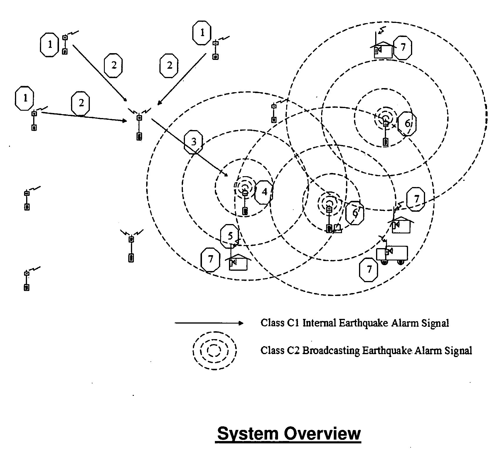
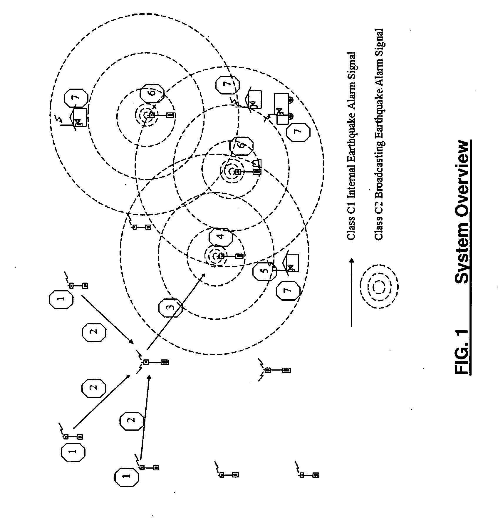
[0009]An aspect of the present invention is to substantially address all of the above problems and / or disadvantages. Accordingly, this invention is to provide an improved area earthquake warning system based on distributed decision making method built on top of relay mode wireless communication. Its self-check mechanism can eliminate system malfunction time. This invention can provide seconds, even tens of seconds early warning window. The system overview is shown in FIG. 1. Such an area earthquake warning system can be affordable in the region where wired and wireless mobile communication infrastructures are too expensive to build.
[0017]According to one aspect of the present invention, a redundant method is used in both the signal format and the frequency channels of wireless communication to increase the reliability of said data links.

Problems solved by technology

This kind of system requires huge data transfer and high computation power, so it can't meet the low cost and real time expectations.
System cost will drastically increase as coverage range expands.
Short wave is cheap and support no-relay wireless communication which is within 30 km (by ground wave) or over 100 km (by sky wave) range, leaves 30˜100 km range as “blind spot”; Satellite can cover wireless communication of any range, but too expensive; Mobile network also can support wireless communication of any range as far as cell base station is available nearby, plus it may take up to minutes to get communication channel granted, especially during heavy call volume period.
All in all, technologies discussed above are insufficient to build an affordable earthquake warning system in the region where wired and wireless mobile communication infrastructures are too expensive to build.

Method used


Image

  • Distributed Decision Making Area Earthquake Warning System
  • Distributed Decision Making Area Earthquake Warning System
  • Distributed Decision Making Area Earthquake Warning System

Examples


Embodiment Construction

[0033]Following description with reference to the accompanying drawings is provided to assist in a comprehensive understanding of the exemplary embodiments of the present invention as defined by the claims and their equivalents. It includes various specific details to assist in that understanding but these are to be regarded as merely exemplary. Accordingly, those of ordinary skill in the art will recognize that various changes and modifications of the embodiments described herein can be made without departing from the scope and spirit of the invention. Also, descriptions of well-known functions and constructions are omitted for clarity and conciseness.

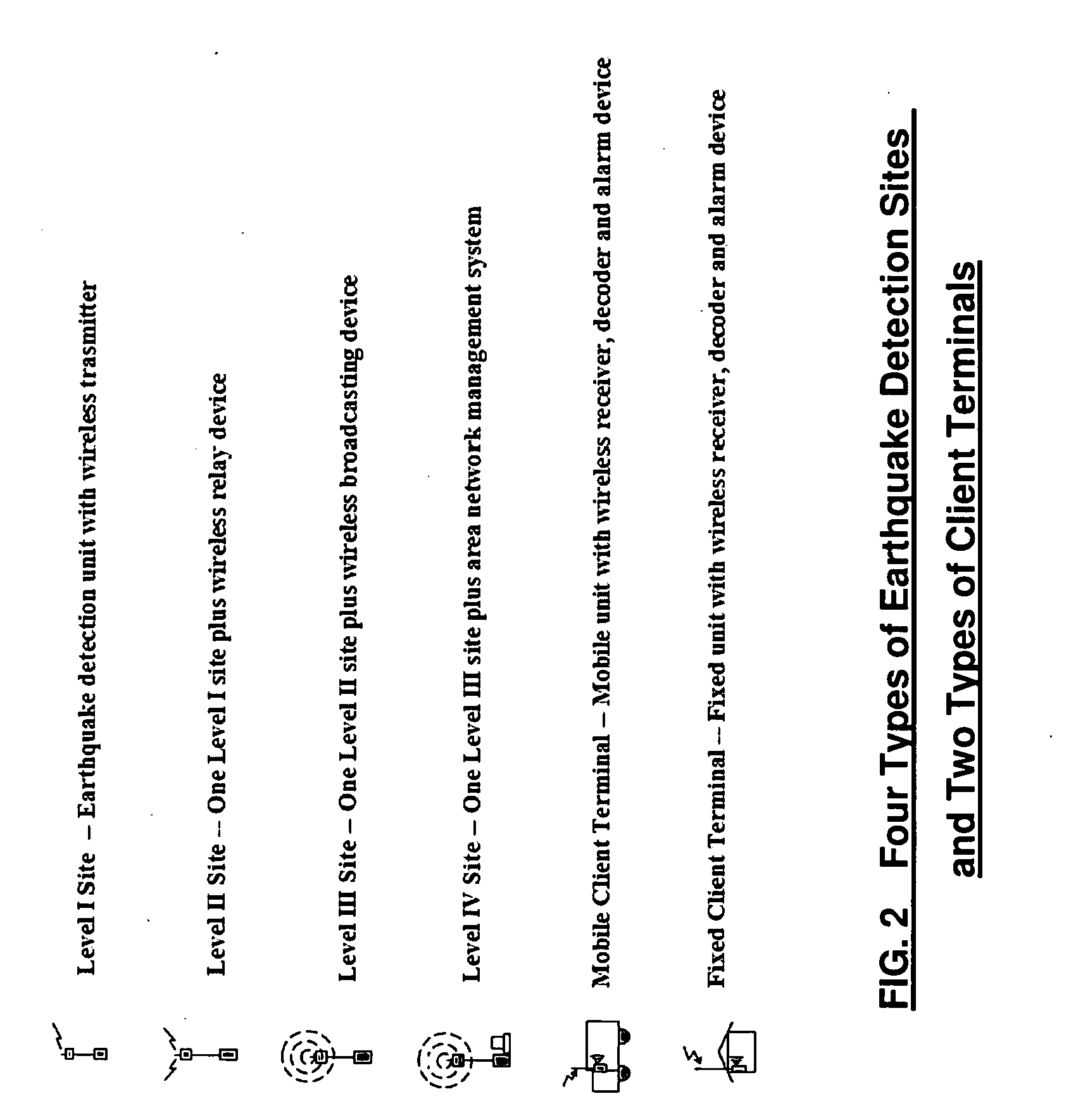
[0034]Referring to FIG. 1, present invention implements an affordable area earthquake warning system based on distributed decision making method. This invention comprises a network of earthquake detection sites covering a geographic region with four types of earthquake detection sites. Instead of sending all raw ground motion signals ...


PUM


Abstract

An improved area earthquake warning system based on distributed decision making method, which makes such a system affordable in the region where wired and wireless mobile communication infrastructures are too expensive to build. The present invention can provide seconds, even tens of seconds for users to seek shelter to reduce injuries and lives lost. An exemplary embodiment of the invention described herein comprises a network of earthquake detection sites covering a geographic region with four types of earthquake detection sites. Instead of sending all raw ground motion signals to a remote central processing site, these detection sites send processed earthquake parameters to a nearby alarm site to decide if an earthquake alarm broadcasting should be triggered. This method shortens the response time, decreases the false alarm rate, and provides unlimited scalability. Further more, this invention provides self-check mechanism to eliminate system malfunction time.

Description

FIELD OF INVENTION[0001]Present invention relates to an earthquake warning system. As well known, it is extremely difficult to rationally forecast a short or medium term earthquake. However, since electromagnetic wave's propagation speed (about 300K km / s) is much faster than destructive seismic waves (about 3 km / s), theoretically it's possible to build an earthquake warning system, by continuously monitoring and detecting earthquake occurrence near epicenter in real time and accurately determining earthquake parameters, to provide seconds, even tens of seconds warning window to epicenter periphery area. This invention provides an affordable area earthquake warning system based on distributed decision making method. An exemplary embodiment of the invention described herein comprises a network of earthquake detection sites covering a geographic region with four types of earthquake detection sites. Instead of sending all raw ground motion signals to a remote central processing site, th...

Claims


Application Information

Patent Timeline
IPC IPC(8): G08B21/00
CPCG08B27/00G08B21/10
Inventor ZHANG, JIEHAN, YUTIAN, FANG
Owner ZHANG JIE
Learn More