Surface illuminator and liquid crystal display using same

a surface illuminator and liquid crystal display technology, applied in the direction of lighting and heating apparatus, instruments, lenses, etc., can solve the problems of uniform luminance, extreme deterioration of the display image, and example of using laser light sources in backlight illumination, etc., to reduce speckle noise, uniform luminance over a large area, excellent color purity

Inactive Publication Date: 2009-12-10
PANASONIC CORP
View PDF4 Cites 56 Cited by
  • Summary
  • Abstract
  • Description
  • Claims
  • Application Information

AI Technical Summary

Benefits of technology

[0074]According to a surface illuminator and a liquid crystal display of the present invention, a laser beam is deflected and scanned at a specific deflection scanning angle, thus making it possible to have a uniform luminance over a large area and also reduce a speckle noise. Further, since a laser light source has excellent color purity, the liquid crystal display with excellent reproduction property and high image quality can be realized. Further, since an emission efficiency of a laser is high, it is possible to exhibit a large advantageous effect that low power consumption is possible as a whole and further higher image quality and low power consumption can be realized.
[0075]In addition, according to the surface illuminator and the liquid crystal display of the present invention whereby a large display screen is realized, in-surface uniform luminance can be maintained even when a light source is deteriorated, and a color separation mechanism is provided for emitting each light to each region corresponding to the pixel of each color of the liquid crystal display. Therefore, saving of power consumption can be achieved.

Problems solved by technology

When there is a variation in luminance, a displayed image is extremely deteriorated even though the color reproduction range becomes wider.
However, there is almost no example of using a laser light source in backlight illumination, and Patent Document 3 neither describes nor discloses a way to realize a uniform luminance.
The laser beams outputted from a laser has a significantly high coherence, and therefore mutual interference allows a random intensity variation to occur, thus forming the speckle noise.
When the speckle noise occurs, deterioration of the image quality of the displayed image is invited.
However, Patent Documents 1, 2, and 3 mentioned above do not show a method of preventing the speckle noise, when the laser is used in the light source as the illuminator for backlight.

Method used


Image

  • Surface illuminator and liquid crystal display using same
  • Surface illuminator and liquid crystal display using same
  • Surface illuminator and liquid crystal display using same

Examples


first embodiment

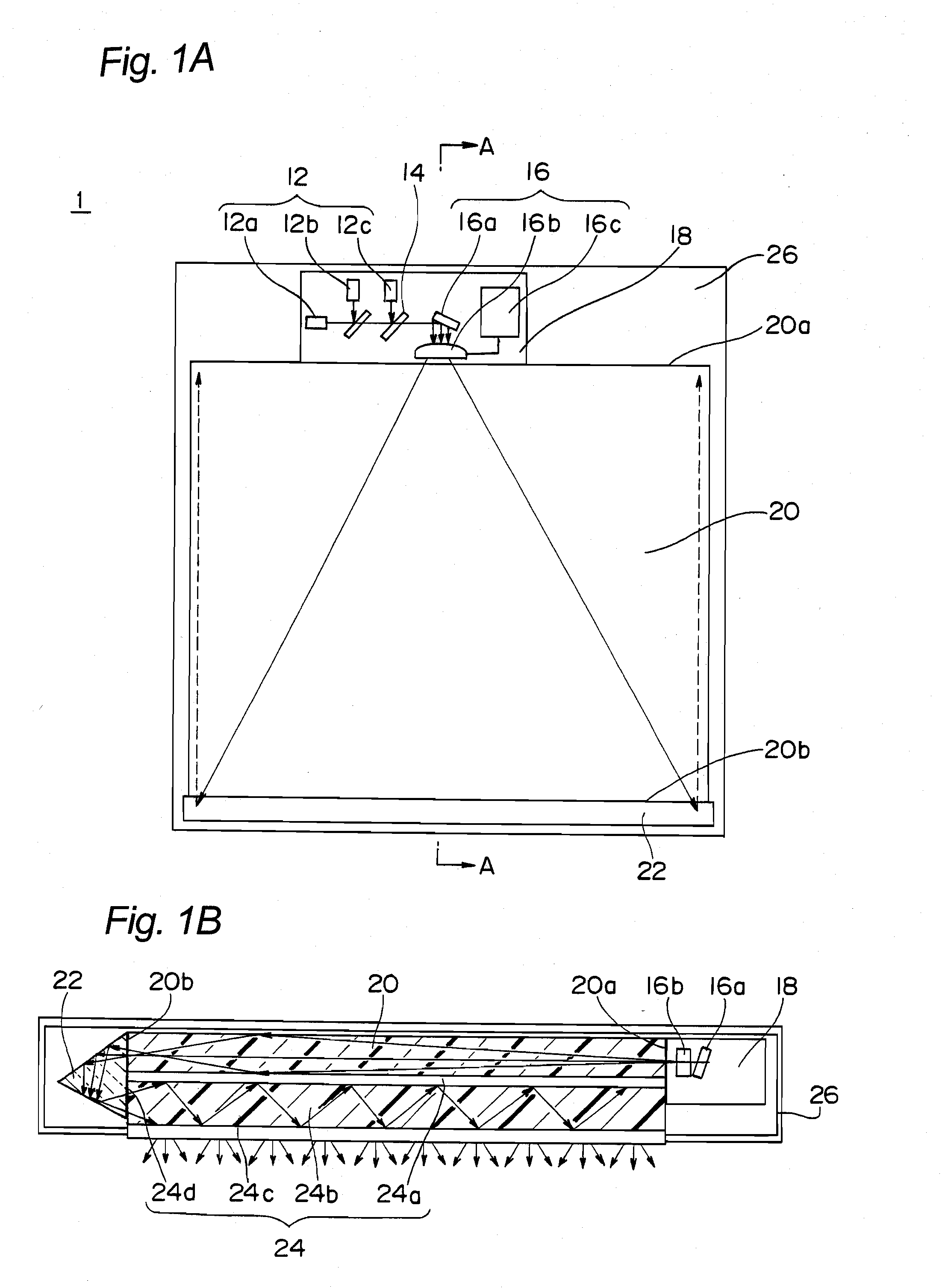
[0135]FIG. 1A and FIG. 1B are diagrams illustrating a surface illuminator according to a first embodiment of the present invention. FIG. 1A is a plan view illustrating an outline of the structure, and FIG. 1B is a schematic sectional view along the line A-A of FIG. 1A.

[0136]As illustrated in FIG. 1A, the surface illuminator 1 of the first embodiment has a structure as described below. A surface illuminator 1 has laser light sources 12a, 12b, and 12c. A laser light source 12 has three light sources such as a red light (R-light) source 12a, a green light (G-light) source 12b, and a blue light (B-light) source 12c that emit light of three primary colors.

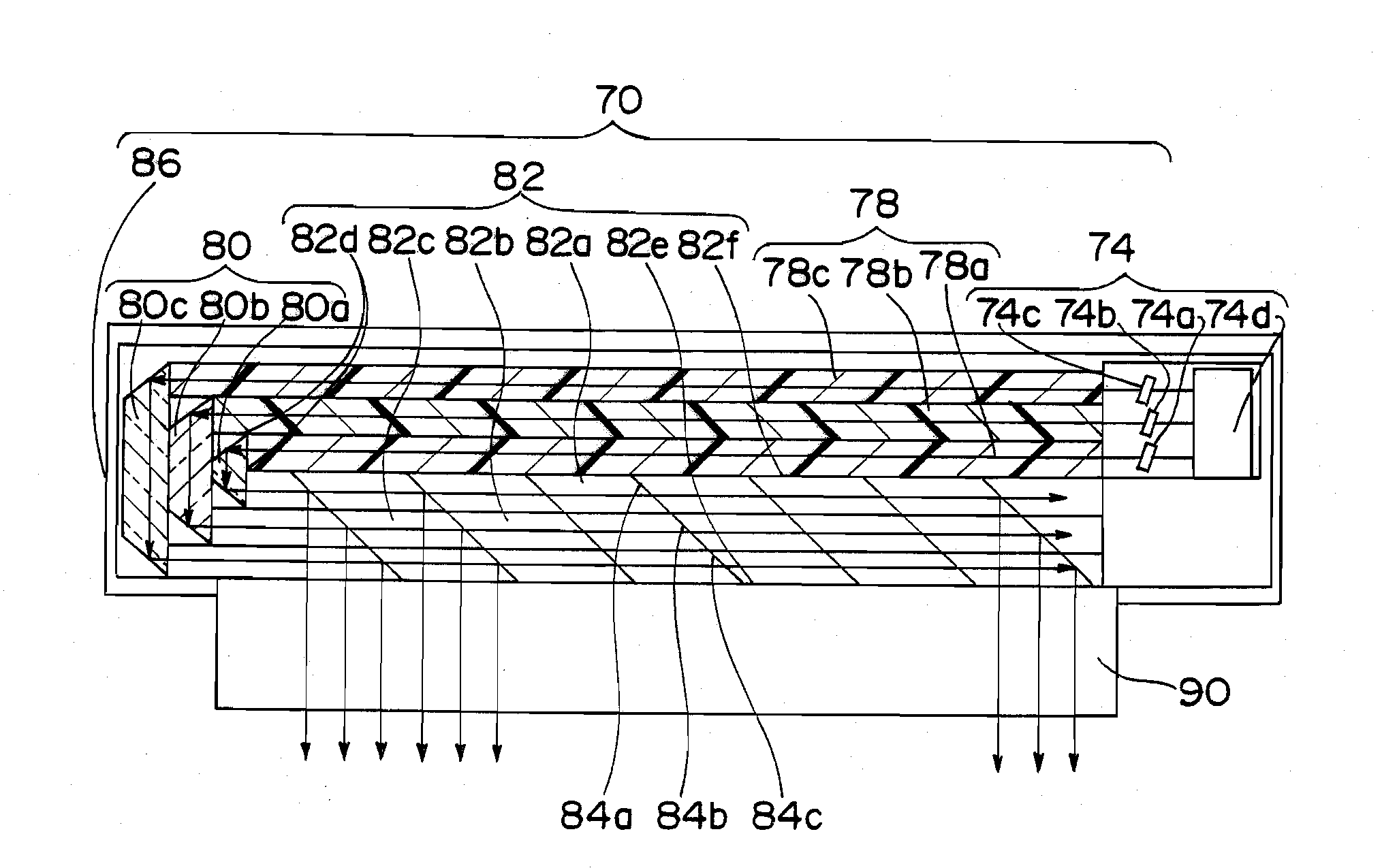
[0137]In addition, when FIG. 1B is referred, the surface illuminator 1 includes a first plate-shaped light guide (first light guide) 24 whereby the laser beam emitted from the laser light sources 12a to 12c is made to be incident from end face portion 24d, and are made to emit from a major surface. When FIG. 1A is referred again, the su...

second embodiment

[0161]FIG. 4A and FIG. 4B are diagrams illustrating a surface illuminator 2 according to a second embodiment of the present invention. FIG. 4A is a schematic plan view illustrating the structure, and FIG. 4B is a schematic sectional view along the line B-B of FIG. 4A.

[0162]The surface illuminator 2 of the second embodiment is different from the surface illuminator 1 of the first embodiment in the point that a structure of a first light guide plate 36 is different from the structure of the first light guide plate 24. Namely, in the second embodiment, a plurality of semi-transmissive mirrors 36a are arranged inside the first light guide plate 36 at a constant pitch. Then, the laser beam incident on the first light guide plate 36 are partially reflected by the semi-transmissive mirrors 36a, in a direction of a major surface (direction of the diffusion plate 36b) of the first light guide plate 36. Note that, in the semi-transmissive mirrors 36a, their reflectances are differentiated at ...

third embodiment

[0164]FIG. 5 is a schematic plan view illustrating a structure of a surface illuminator 3 according to a third embodiment of the present invention. Also in this illustration for the surface illuminator 3, each surface of the casing 26 and the housing 18 is cut out, thereby making it easy to understand an internal structure.

[0165]The surface illuminator 3 of the third embodiment has a beam scan section 38 having a different structure from that of the beam scan section 16 of the first embodiment. In fact, the cylindrical lens 16b is used in the beam scan section 16 of the surface illuminator 1 of the first embodiment. However, in the surface illuminator 3 of the third embodiment, instead of the cylindrical lens 16b, a lenticular lens 38b is used. The laser beam is reflected by the reflection mirrors 38a of the beam scan section 38, and then made to be incident on the lenticular lens 38b. The laser beam incident onto the lenticular lens 38b is spread one-dimensionally and is made to be...


PUM

PropertyMeasurementUnit
timeaaaaaaaaaa
opticalaaaaaaaaaa
angleaaaaaaaaaa

Abstract

The present invention provides a surface illuminator having a uniform luminance over a large area by using a laser light source, having a wide color reproduction range, and capable of suppressing a speckle noise, as well as a liquid crystal display using the same. The surface illuminator of the present invention includes the laser light source that emits a laser beam; a beam scan section that deflects and scans the laser beam; and a first plate-shaped light guide that makes the laser beam deflected and scanned by the beam scan section to be incident from an end face portion and making the incident laser beam to emit from a first major surface. Further, the liquid crystal display of the present invention includes a liquid crystal display panel and the surface illuminator, wherein the surface illuminator is used as a backlight illuminator that lights the liquid crystal display panel from backside in this liquid crystal display.

Description

TECHNICAL FIELD[0001]The present invention relates to a surface illuminator using a laser beam as a light source, and a liquid crystal display using the surface illuminator.BACKGROUND ART[0002]Conventionally, the surface illuminator using a cold cathode fluorescent tube as a light source is widely used as a backlight illumination in the liquid crystal display using a liquid crystal display panel. The cold cathode fluorescent tube used therein utilizes light emission of a phosphor (fluorescent material), and has a restriction in a displayable color reproduction range. Therefore, various examinations have been carried out for reproducing a further clear and natural tone. Above all, the surface illuminator for backlight using a light emitting diode (an LED element) of three colors such as red light (R-light), green light (G-light), and blue light (B-light) is focused. The light source using the three colors of R-light, G-light, and B-light or a multi-color LED element has a wider color...

Claims


Application Information

Patent Timeline
Patent Type & Authority Applications(United States)
IPC IPC(8): F21V8/00G02F1/13357
CPCG02B3/0056G02B5/02G02B6/0028G02B6/0066G02B26/105G02B27/1053G02B19/0028G02B27/144G02B27/145G02B27/48G02F1/133621G02B19/0057G02B27/1086
Inventor MIZUSHIMA, TETSUROKASAZUMI, KEN'ICHIMIZUUCHI, KIMINORIYAMAMOTO, KAZUHISAKADOWAKI, SHIN-ICHIITOH, TATSUO
Owner PANASONIC CORP
Why Eureka
Try Eureka