Battery pack

a battery pack and battery technology, applied in the field of batteries, can solve the problems of reducing the life of batteries, reducing the service life of batteries, so as to improve the strength of the case

Inactive Publication Date: 2009-12-10
KK TOSHIBA
View PDF5 Cites 36 Cited by
  • Summary
  • Abstract
  • Description
  • Claims
  • Application Information

AI Technical Summary

Benefits of technology

[0011]The present invention was conceived in consideration of the foregoing problems, and it is an object of the present invention to provide a battery pack which is capable of monitoring voltages of respective cells from outside the case and which is excellent in strength against an impact and a fire accident.
[0016]The present invention allows voltages of respective cells to be monitored from outside the case, and therefore, the respective cells may be completely prevented from being overcharged. Use of a metal case as an outer case can remarkably improve the strength of the case and provides safety state against an external impact and burst even at an internal fire accident.

Problems solved by technology

However, conventional battery packs constructed as described above have some problems to be solved.
That is, the battery pack as proposed in the Patent Publications has such a drawback that, where a lithium ion secondary battery is used as a cell housed in the battery pack, the cell possibly bursts due to overcharge and causes leakage of the petroleum solvent housed inside, which may lead to firing.
Hence, charging current passes through fully changed, which causes overcharge.
None of the conventional techniques described in the respective Patent Publications has any measures against overcharge caused by a different charging degree between the respective cells as described above, remaining the possibility of bursting the cells by overcharging.
Furthermore, in a secondary battery such as a lithium ion battery, if moisture is permeated into the battery, the lifetime thereof is remarkably shortened.
However, a permeable water amount differs depending upon sealing quality at every battery enclosure, which causes the housed cells to have a lifetime different from each other.
However, the conventional technique in the Patent Publication 3, using a sheet-shaped member formed by laminating a plurality of types of raw materials as a case, causes the case itself to have poor rigidity, which cannot fully deal with an external impact or an internal fire accident.

Method used


Image

  • Battery pack
  • Battery pack
  • Battery pack

Examples


first embodiment

(1) FIRST EMBODIMENT

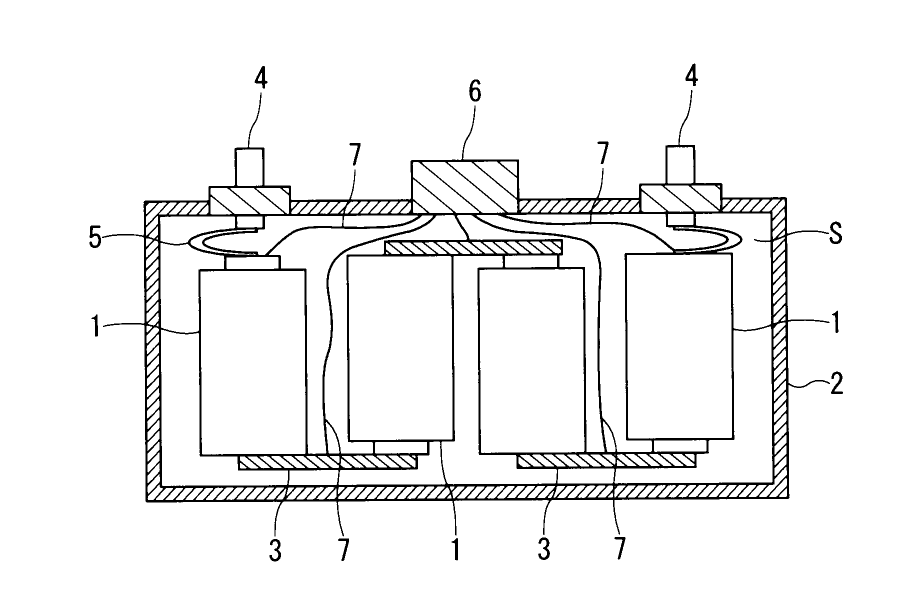
[0022]A first embodiment shown in FIG. 1 illustrates a basic configuration of the present invention. The embodiment is provided a plurality of cells, and a columnar cell, as each cell 1, having a positive (+) terminal and a negative (−) terminal at upper and lower ends thereof is used. The plurality of cells 1 are housed in an airtight and watertight metal case 2 of a press molded or cast article made of iron or aluminum.

[0023]The plurality of cells 1 are housed with the vertical orientation thereof alternately changed in the metal case 2, and one negative terminal thereof is connected to one positive terminal, respectively, through a connection member 3 for a serial electrical connection. The metal case 2 has positive-side and negative-side external terminals 4, and the external terminals 4 and terminals of the cells 1 are connected to each other through lead wires 5.

[0024]To the metal case 2, a voltage monitoring connector 6 is attached, and a voltage taking wi...

second embodiment

(2) SECOND EMBODIMENT

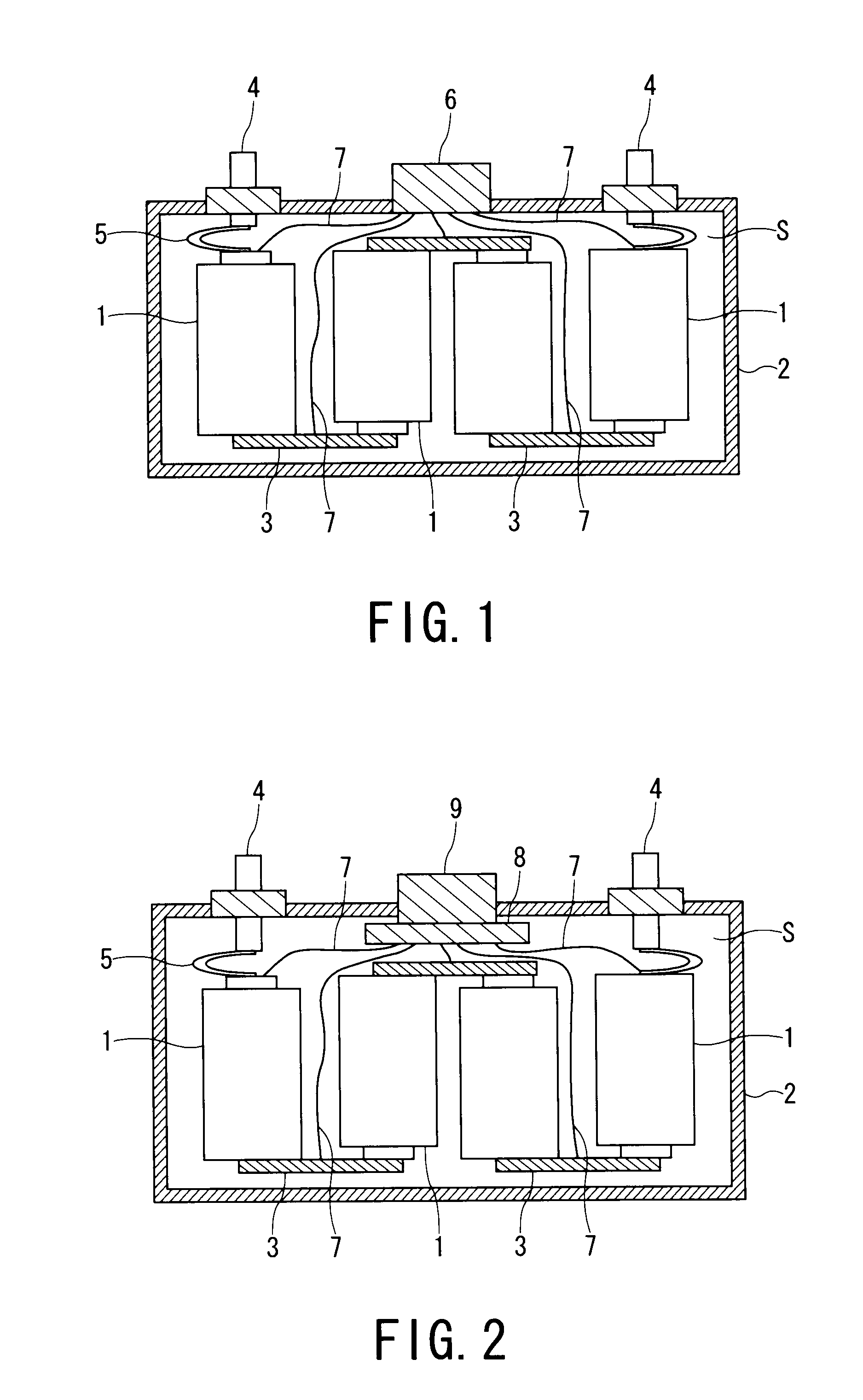
[0029]While the first embodiment is configured so as to directly take out the voltages of respective cells 1 into a voltage monitoring connector 6, a second embodiment is configured so as to provide a voltage monitoring electronic circuit 8 in a metal case 2 to collect information concerning:[0030](a) a cell or cells under an overcharging state,[0031](b) availability of charging to battery pack,[0032](c) charging degree of each cell and[0033](d) battery lifetime,

[0034]Such information is taken out to the outside of the metal case 2 via an information communicating connector 9.

[0035]According to the second embodiment, an improved controlling of the charging time and the lifetime of the battery can be performed over the first embodiment because other information of each cell and the whole battery pack can be acquired by the connector 9 in addition to detection of voltage of each cell.

[0036]The other configurations or structures are the same as those in the first e...

third embodiment

(3) THIRD EMBODIMENT

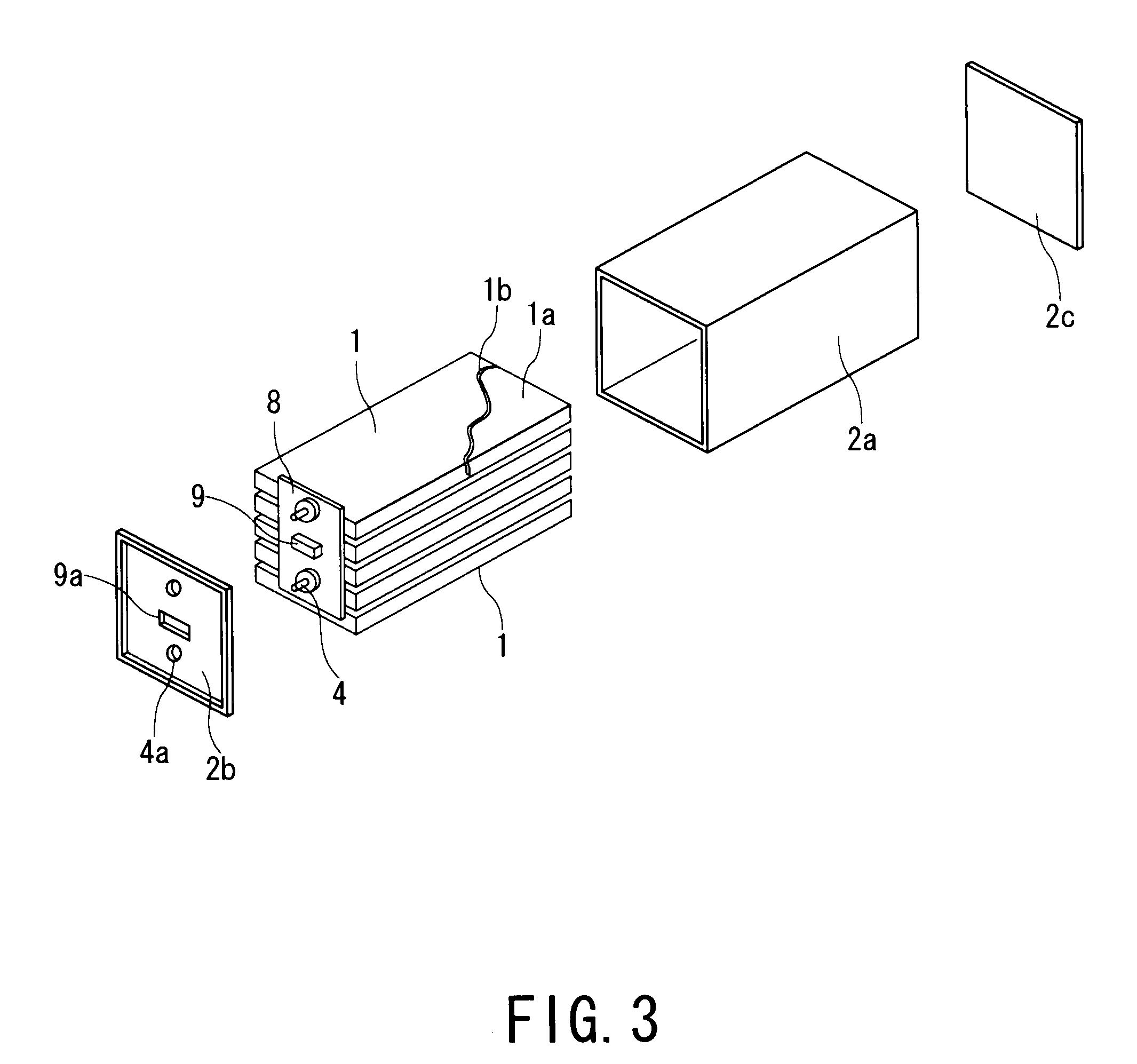
[0037]A third embodiment illustrated in FIG. 3 is configured to laminate and house a plurality of thin plate-like cells 1 in a metal case 2. In this case, each cell 1 has a structure to seal cell bodies 1a into a cover member 1b such as polyethylene, polypropylene, polyethylene terephthalate (PET), polycarbonate or acrylonitrile-butadiene-styrene (ABS), and a positive terminal and a negative terminal are drawn out of one side of the cover member 1b and electrically connected to each other by such means as crimping or welding.

[0038]At an end portion of the laminated cell 1, a monitoring electronic circuit 8 and a connector 9 for transmitting / receiving information, and positive-side and negative-side external terminals 4 as illustrated in the second embodiment are integrally attached.

[0039]As a metal case 2, a box-like case constituted by a tubular case body 2a and lid plates 2b, 2c provided at the front and rear end of the case body 2a is used. In this case, the f...


PUM

PropertyMeasurementUnit
electric currentaaaaaaaaaa
voltageaaaaaaaaaa
voltagesaaaaaaaaaa

Abstract

Negative (−) terminals and positive (+) terminals of a plurality of cells in a connected state are housed in a metal case. The metal case is attached with positive-side and negative-side external terminals, and the external terminals and cell terminals are connected with each other through lead wires. The metal case is attached with a voltage monitoring connector, and the voltage monitoring connector and a voltage taking electric wires extending from the positive and negative sides of the respective cells are connected with each other. Through the voltage monitoring connector, the charging degrees of the individual cells can be obtained, thereby preventing the cells from being overcharged.

Description

TECHNICAL FIELD[0001]The present invention relates to a battery pack housing a plurality of cells in a case, and in particular, relates to a battery pack having a voltage monitoring connector for monitoring voltages of the cells sealed in the case.BACKGROUND ART[0002]As a battery pack housing a plurality of cells in a case, there have been such conventionally known battery packs as disclosed in Patent Publication 1 (Japanese Patent Application Laid-Open No. 2004-146161) and Patent Publication 2 (Japanese Patent Application Laid-Open No. 2004-55346).[0003]The Patent Publication 1 has proposed a technique of a battery pack that prevents vibration of cells by disposing an elastic material between cells and a case.[0004]The Patent Publication 2 has proposed a battery pack structured so as to house a plurality of cells in a case and to dispose gel adhesive or a rubber seat between the cells and the case.[0005]Patent Publication 3 (Japanese Patent Application Laid-Open No. 2001-68074) has...

Claims


Application Information

Patent Timeline
Patent Type & Authority Applications(United States)
IPC IPC(8): H01M6/42H01M50/51
CPCH01M2/105H01M10/482H01M10/425H01M2/204Y02E60/10H01M50/213H01M50/51
Inventor KOSUGI, SHINICHIROOZAKI, TAMONARAOKA, KATSUMASA
Owner KK TOSHIBA
Why Eureka
Try Eureka