Method and apparatus for control of cooling system air quality and energy consumption

a technology for cooling systems and air quality, applied in the direction of domestic cooling apparatus, ventilation systems, heating types, etc., can solve the problems of limited sophistication in energy saving features, no retrofit exists for literally millions of existing air conditioning units, and the operating cost (energy use) of the system has not been a significant consideration. , to achieve the effect of reducing energy consumption

Active Publication Date: 2009-12-17
PATCH RONALD HARRISON
View PDF24 Cites 68 Cited by
  • Summary
  • Abstract
  • Description
  • Claims
  • Application Information

AI Technical Summary

Benefits of technology

[0006]The control systems of the present invention advantageously reduce energy consumption of conventional forced air heating and cooling systems, hot and cold air drafts, noise associated with fan or blower operation, and indoor CO2 levels.

Problems solved by technology

The operating cost (energy use) of the systems has not been a significant consideration until recently, with the current focus on energy consumption and its link to both global warming and increased costs.
As air conditioning units go, single-zone package units have been considered to be a commodity item and, as such, they have limited sophistication when it comes to energy saving features.
Current state-of-the-art air conditioning units are becoming more energy efficient by using variable airflow, improved heat transfer surfaces, more efficient fans, and more efficient compressors, but no retrofit exists for the literally millions of existing air conditioning units that could operate with less energy without sacrificing comfort.

Method used


Image

  • Method and apparatus for control of cooling system air quality and energy consumption
  • Method and apparatus for control of cooling system air quality and energy consumption
  • Method and apparatus for control of cooling system air quality and energy consumption

Examples


first embodiment

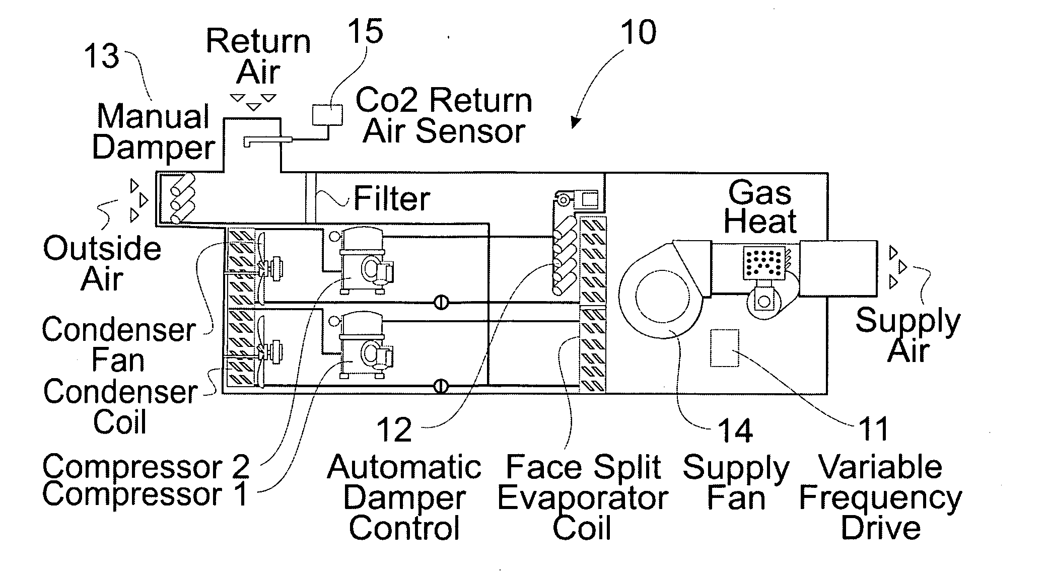
[0037]In the present invention for use with face split coils, automatic control dampers are added to prevent air bypass through the de-energized coil face at partial cooling loads. The damper is only closed during partial cooling loads in order to keep the air pressure drop through the cooling coil to a minimum. This minimization of the air pressure drop further reduces the fan energy usage. The fan speed is indexed to proportionally match the face area of the energized coil, so the active coil face velocity is identical to the coil face velocity at maximum load. As a result, all the heat transfer characteristics of the active cooling coil are essentially unchanged. These characteristics are suction pressure, superheat, sub-cooling, sensible and latent cooling capacities, and airside pressure drop.

second embodiment

[0038]In the present invention for use with interlaced coils, suction pressure control is used to maintain adequate airflow at partial loads. At partial load conditions, the fan speed is reduced in proportion to the remaining cooling capacity percentage. Depending on the amount of outside air being brought into the forced air heating / cooling system and the enthalpy of the outdoor air, there are times when the suction pressure could drop into the unacceptable ranges on an interlaced coil since the face velocity has been reduced by as much as half. In this case, the present invention increases the fan speed as required to maintain the suction temperature and therefore the suction pressure in the acceptable range. Neither of these two methods are currently employed in the air conditioning industry.

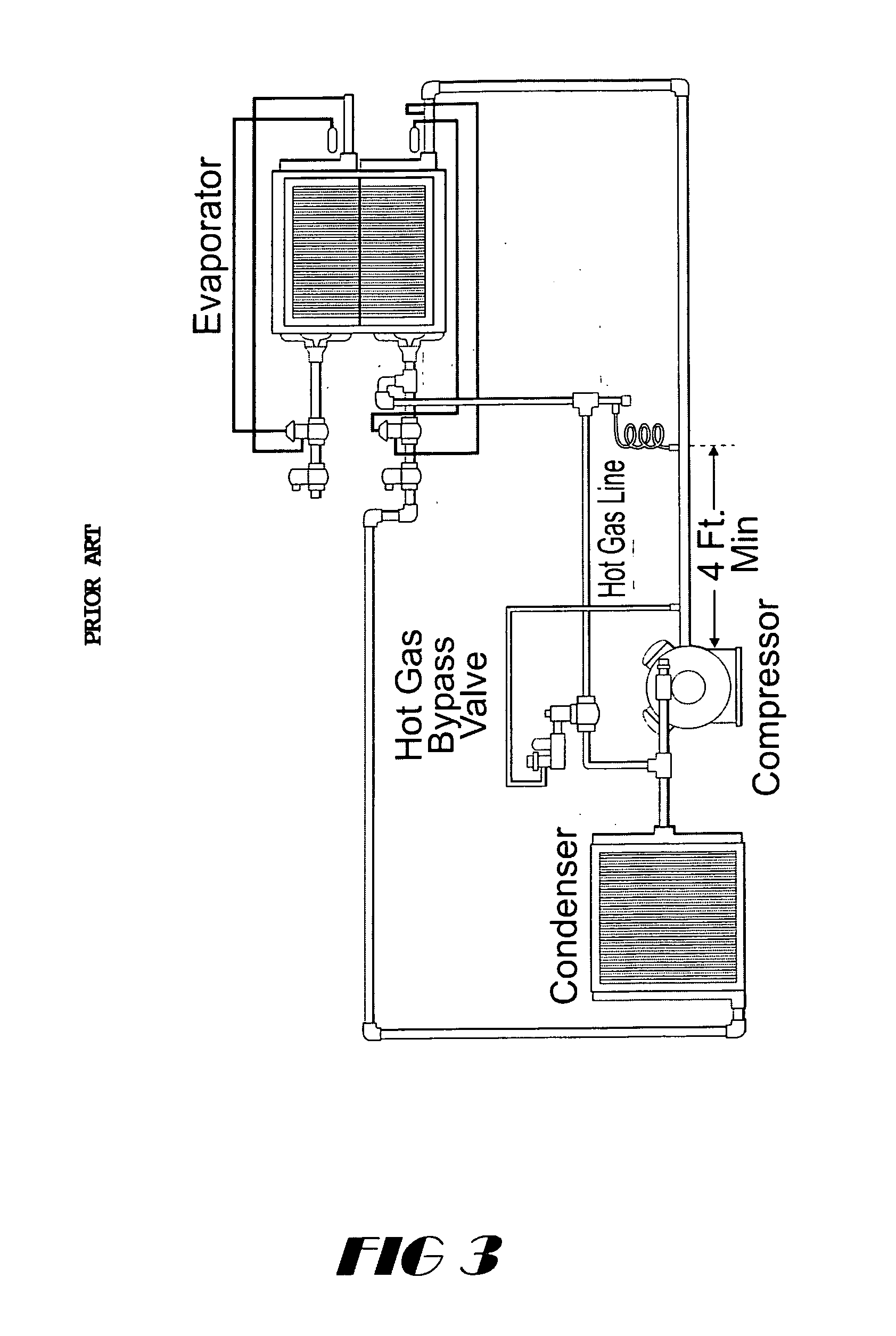
[0039]Regardless of the cooling coil circuiting, in either case, suction pressure will be maintained at acceptable levels without the use of expensive first cost, energy inefficient, and diff...


PUM


Abstract

An energy saving air quality control system modulates supply fan speed by use of controlled, variable-frequency drive controls for automatic dampers or suction pressure to maintain adequate air flow across the evaporator coil at partial cooling loads. Demand ventilation in the system balances air quality and energy consumption by controlling the outdoor air damper in response to indoor CO2 levels. The control system variously either (1) produces a variable 0-10 VDC output signal to modulate the outside ventilation air damper as required to keep the CO2 concentration below a set point; (2) produces a 0 or 24 VAC signal to either open or close a two-position outside air damper for as long a time period as is required in order to keep the CO2 concentration below a set point; or (3) allows manually setting the outside air damper to provide proper ventilation air at maximum occupancy and maximum air flow and modulates the supply fan speed as required to keep the CO2 concentration as measured by a CO2 monitor below set point.

Description

FIELD OF THE INVENTION[0001]The present invention pertains to a control system for varying the speed of a fan drive motor for a forced air indoor space heating / cooling system during all modes of operation of the heating / cooling system.BACKGROUND OF THE INVENTION[0002]Single-zone rooftop units have been used worldwide for the last 40 years on small office buildings, shopping malls, and retail stores. Single-zone air conditioning units have long been the lowest first-cost method of air conditioning buildings. The operating cost (energy use) of the systems has not been a significant consideration until recently, with the current focus on energy consumption and its link to both global warming and increased costs.[0003]As air conditioning units go, single-zone package units have been considered to be a commodity item and, as such, they have limited sophistication when it comes to energy saving features. Current state-of-the-art air conditioning units are becoming more energy efficient by...

Claims


Application Information

Patent Timeline
Patent Type & Authority Applications(United States)
IPC IPC(8): F24F7/00
CPCF24F11/0001F24F11/0017Y02B30/78F24F2011/0026Y02B30/746F24F11/0079F24F11/30F24F2110/50F24F2110/70F24F11/77Y02B30/70F24F11/46
Inventor PATCH, RONALD HARRISON
Owner PATCH RONALD HARRISON
Why Eureka
Try Eureka