
Method for distance measurement and data transmission in a continuous wave radar system

a radar system and distance measurement technology, applied in the direction of reradiation, measurement devices, instruments, etc., can solve the problems of large disruption of the reception of radio response signals, difficulty in determining the distance to a specific object, so as to improve the comfort and safety of the control operation of the operator.

Active Publication Date: 2009-12-17
SIEMENS AG
View PDF12 Cites 21 Cited by
  • Summary
  • Abstract
  • Description
  • Claims
  • Application Information

AI Technical Summary

Benefits of technology

[0015]An object of the invention is to develop a continuous wave radar system in such a way that a distance measurement between a transponder device and a transmit and receive module as well as a data transmission from the transponder device to the transmit and receive module can be reliably performed, in particular without affecting other systems.

Problems solved by technology

The use of a radar system for determining the distance to a specific object is sometimes problematic, since multifarious external factors can have a substantial adverse effect on or interfere with the reception of reflected radar signals.
Particularly in the presence of reflecting metal surfaces or bodies which absorb radar beams it is only possible to a limited degree to assign a received radar signal to a specific reflecting object.
The use of a single transponder appears disadvantageous in particular in view of constantly changing ambient conditions.
If, for example, the transponder and the receive module of the radar system are moving or absorbing or shadowing bodies are temporarily situated between the transponder and the receive module, this causes massive disruption to the reception of radio response signals as well as to the sending of interrogation signals to the transponder, with the result that determining a distance is no longer possible under certain conditions.
Since, however, the frequency of an FMCW signal is subject to a periodic modulation, it is very probable that adjacent transmit and receive modules which continuously transmit an FMCW signal will mutually affect one another, with the result that no reliable distance measurement can be performed.
Furthermore, a transmit and receive module which constantly transmits an FMCW signal can interfere with other systems operating in the same frequency range, for example a WLAN system.
Of course, these problems also occur when the FMCW signal is transmitted only temporarily.
Moreover, an FMCW signal can also interfere with a data transmission in a continuous wave radar system from a transponder to a transmit and receive module, since the interrogation signal is typically very much stronger than the radio response signal.

Method used


Image

  • Method for distance measurement and data transmission in a continuous wave radar system
  • Method for distance measurement and data transmission in a continuous wave radar system
  • Method for distance measurement and data transmission in a continuous wave radar system

Examples


Embodiment Construction

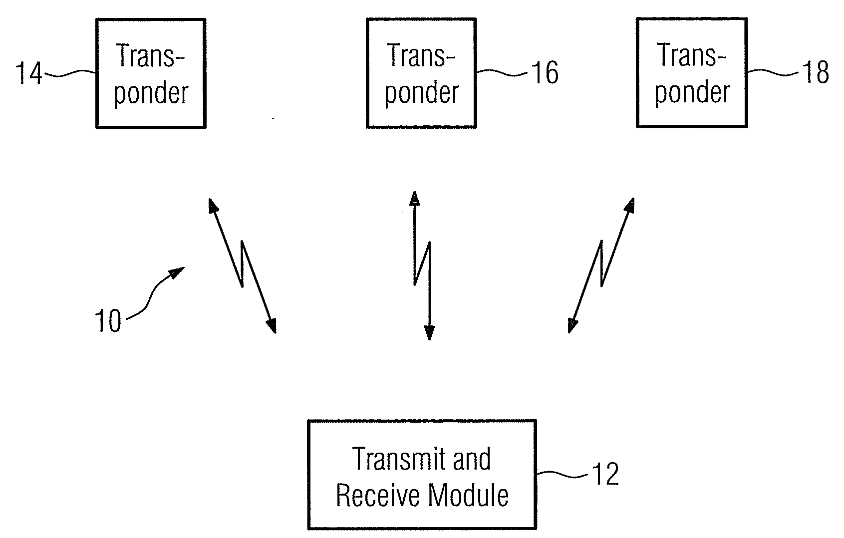
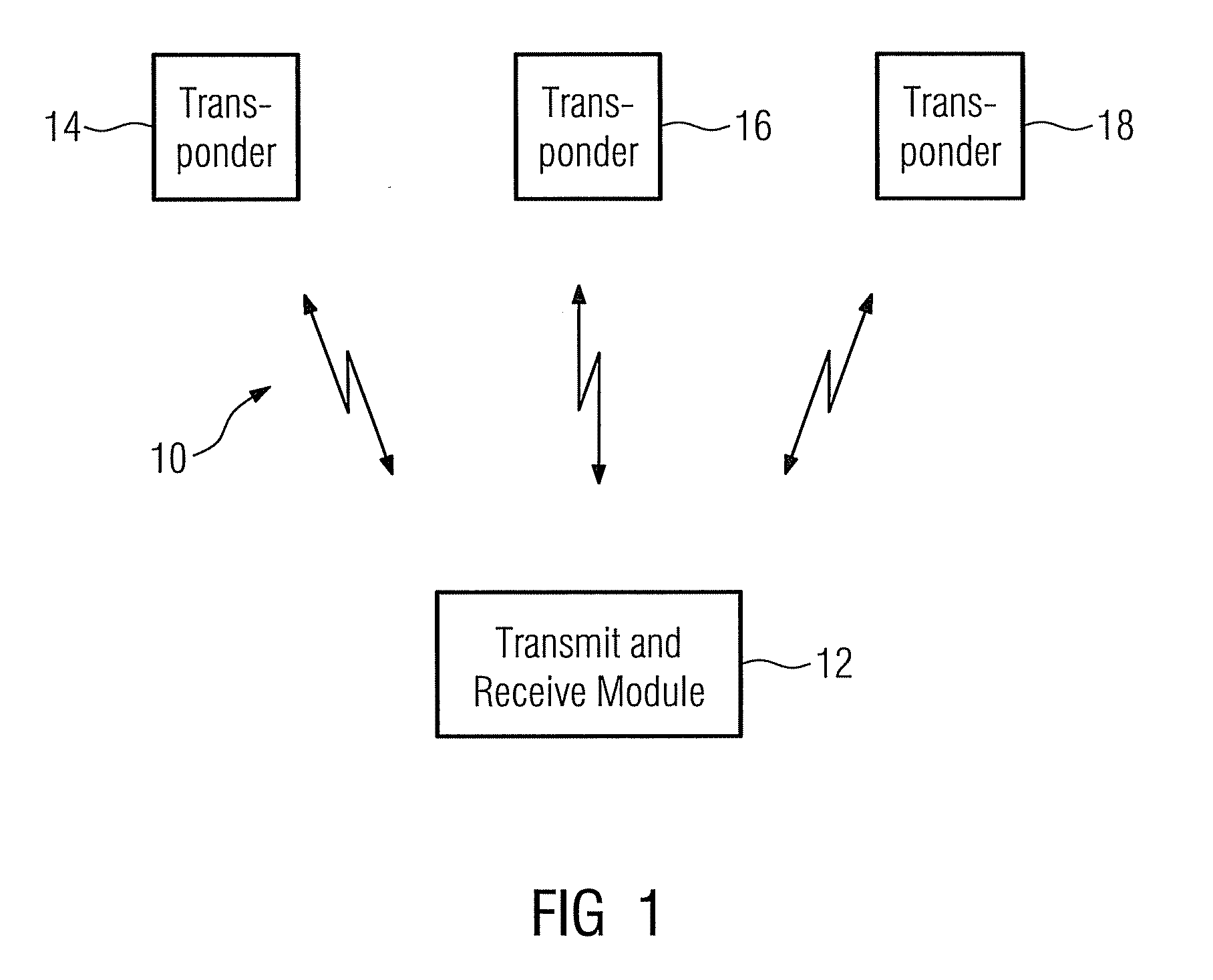
[0035]FIG. 1 shows a schematic block diagram of an exemplary embodiment of a continuous wave radar system 10 which has three transponders 14, 16, 18 and a transmit and receive module 12. The transmit and receive module 12 is configured to transmit interrogation signals which are received by the transponders 14, 16, 18, modulated, amplified if necessary, and sent back again as radio response signals. The carrier frequency of the interrogation signal or, as the case may be, of the radio response signals remains unchanged in this case (referred to as back-scattering) and typically lies in the GHz range, e.g. in the ISM band between 2.400 GHZ and 2.483 GHz.

[0036]The interrogation signal is an unmodulated continuous wave signal (CW signal). However, the transmit and receive module 12 transmits a frequency-modulated continuous wave signal (FMCW signal) instead of the unmodulated continuous wave signal as soon as a transponder has sent a radio response signal in response to the interrogati...


PUM


Abstract

A method for distance measurement and data transmission in a continuous wave radar system is described. A continuous wave radar system has a transmit and receive module and at least one transponder device, a mobile control and monitoring device and an HMI system. Transponder devices are searched for with the aid of an unmodulated continuous wave signal as an interrogation signal, such that the transponder device can send a radio response signal to the transmit and receive module in response to the interrogation signal, as a result of which a data transmission takes place from the transponder device to the transmit and receive module. Upon completion of the data transmission a frequency-modulated continuous wave signal is generated in order to measure, on the basis thereof, a distance between the transponder device and the transmit and receive module.

Description

CROSS REFERENCE TO RELATED APPLICATIONS[0001]This application claims priority of European Patent Application No. 08010824.4 EP filed Jun. 13, 2008, which is incorporated by reference herein in its entirety.FIELD OF INVENTION[0002]The present invention relates to a method for distance measurement and data transmission in a continuous wave radar system. The present invention further relates to a continuous wave radar system having a transmit and receive module and at least one transponder device, a mobile control and monitoring device, and an HMI system.BACKGROUND OF INVENTION[0003]Radar systems are suited to contactless localization and distance determination of objects. Among a multiplicity of different radar systems, e.g. a frequency-modulated continuous wave radar system, also referred to in abbreviated form as FMCW radar, permits reliable distance determination between objects which are also e.g. spaced only a short distance apart from one another. Continuous wave (CW) radar radi...

Claims


Application Information

Patent Timeline
Patent Type & Authority Applications(United States)
IPC IPC(8): G01S13/08
CPCG01S13/34G01S13/876G01S13/825
Inventor ALBERT, OLAFGILA, JANOSHLADIK, REINHARDSCHIEFER, MARTINSPANDL, MANFRED
Owner SIEMENS AG
Learn More