Touch panel using nano-wire

Active Publication Date: 2009-12-17
SAMSUNG ELECTRONICS CO LTD
View PDF2 Cites 37 Cited by
  • Summary
  • Abstract
  • Description
  • Claims
  • Application Information

AI Technical Summary

Benefits of technology

[0007]Example embodiments provide a relatively high performance touch panel using a piezoelectric device hav

Problems solved by technology

In this regard, a PZT thin film may have a relatively high piezoelectric const

Method used


Image

  • Touch panel using nano-wire
  • Touch panel using nano-wire
  • Touch panel using nano-wire

Examples


Embodiment Construction

[0017]Example embodiments will be described more fully hereinafter with reference to the accompanying drawings, in which example embodiments are shown. Example embodiments may, however, be embodied in different forms and should not be construed as limited to example embodiments set forth herein. Rather, example embodiments are provided so that this disclosure will be thorough and complete, and will fully convey the scope of example embodiments to those skilled in the art. In the drawings, the thickness of layers and regions are exaggerated for clarity. Like numbers refer to like elements throughout the specification.

[0018]It will be understood that when an element is referred to as being “connected” or “coupled” to another element, it can be directly connected or coupled to the other element or intervening elements may be present. In contrast, when an element is referred to as being “directly connected” or “directly coupled” to another element, there are no intervening elements pres...


PUM


Abstract

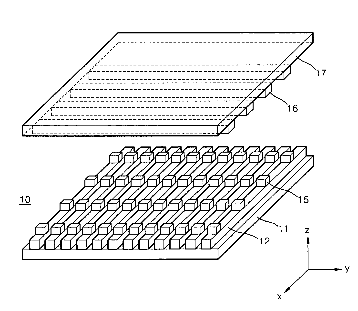
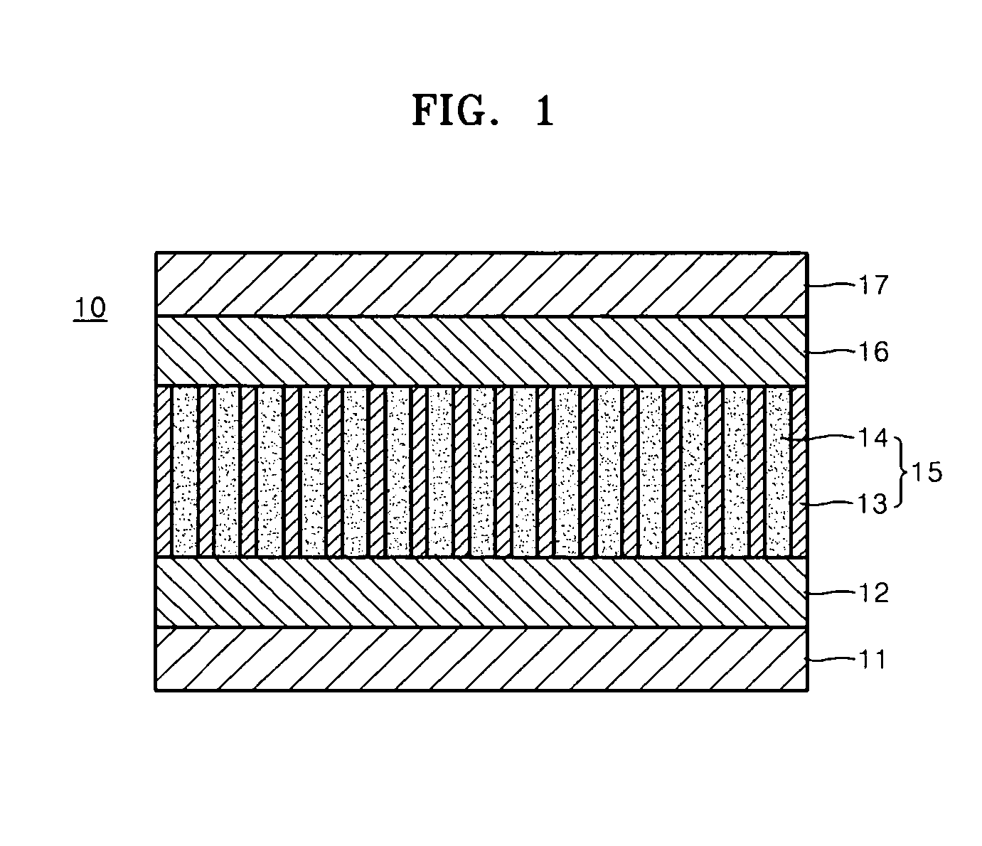
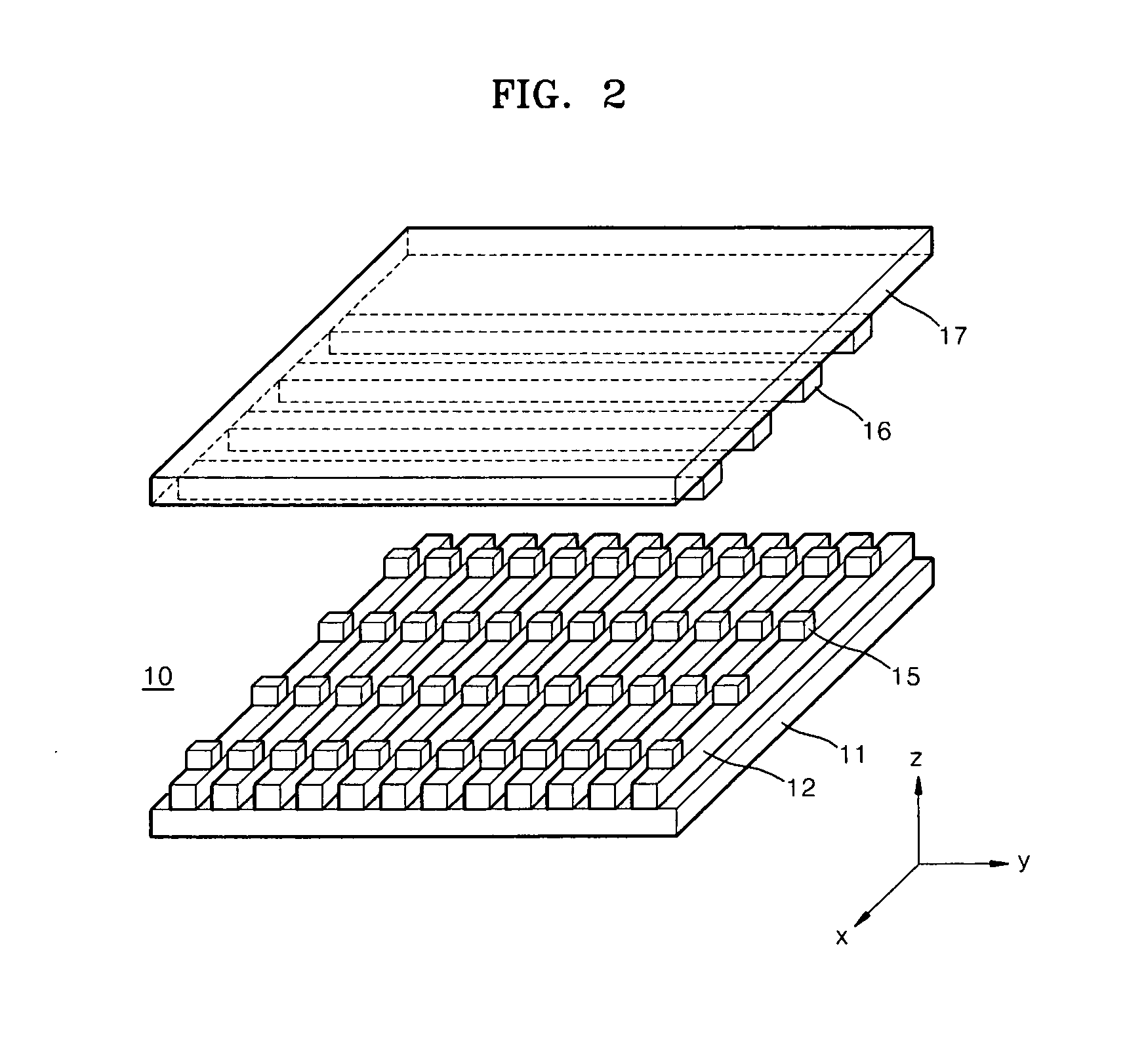
Provided is a touch panel using a zinc oxide (ZnO) nano wire. The touch panel may include a first transparent substrate, a first transparent electrode layer on the first transparent substrate, a light transmissive nano wire layer including a plurality of piezoelectric nano wires that may be arranged on the first transparent electrode layer so as to be perpendicular to the first transparent electrode layer, a second transparent electrode layer on the nano wire layer, and a second transparent substrate on the second transparent electrode layer.

Description

PRIORITY STATEMENT[0001]This application claims priority under U.S.C. § 119 to Korean Patent Application No. 10-2008-0057018, filed on Jun. 17, 2008, in the Korean Intellectual Property Office (KIPO), the entire contents of which are incorporated herein by reference.BACKGROUND[0002]1. Field[0003]Example embodiments relate to a touch panel, and more particularly, to a touch panel using a zinc oxide (ZnO) nano wire.[0004]2. Description of the Related Art[0005]Touch panels may be a type of input device which may be installed on a front surface display of an electronic apparatus (e.g., personal computers, notebook computers, or portable media players (PMPs)) and which input a predetermined or given order or data to the electronic apparatus by an operation of simply touching the display front surface by using fingers or pens, or an operation of inserting characters or pictures on the front surface display. Recently, as consumer demand for convenience has increased, demand for touch panel...

Claims


Application Information

Patent Timeline
IPC IPC(8): G06F3/041
CPCG06F3/0414G06F3/046G06F2203/04103H01B5/14
Inventor KIM, SANGWOOKPARK, YOUNGSOOKIM, CHANGJUNG
Owner SAMSUNG ELECTRONICS CO LTD
Why Eureka
Try Eureka