Driving circuit and display

a driving circuit and display technology, applied in the field of driving circuits and displays, can solve the problems of high harmonics, emi noise in the mhz band, acute rise in charging/discharging current, etc., and achieve the effects of reducing emi noise, high harmonic components, and reducing charging/discharging curren

Inactive Publication Date: 2009-12-17
RENESAS ELECTRONICS CORP
View PDF5 Cites 12 Cited by
  • Summary
  • Abstract
  • Description
  • Claims
  • Application Information

AI Technical Summary

Benefits of technology

[0014]According to the present invention, high harmonic components in the charging / discharging current may be reduced by progressively varying the impedance of the output switching circuit to prohibit acute changes in the charging / discharging current. It is thus possible to reduce the EMI noise ascribable to the high harmonic components in the charging / discharging current.

Problems solved by technology

However, there still persists acute rising in the charging / discharging current.
However, since high harmonics are contained in the acutely rising charging / discharging circuit, these high harmonics are actually presented as EMI noise, with a result that the EMI noise in the MHz band, composed of the high harmonics, is increased. FIG. 5B shows the results of analysis by FFT (Fast Fourier Transform) of the conventional technique.
It is seen from this figure that, although the fundamental frequency component of the charging / discharging current is approximately 50 kHz, the current contains a great deal of high harmonics of 10 MHz to 1 GHz which present problems as EMI noise.

Method used


Image

  • Driving circuit and display
  • Driving circuit and display
  • Driving circuit and display

Examples


example 1

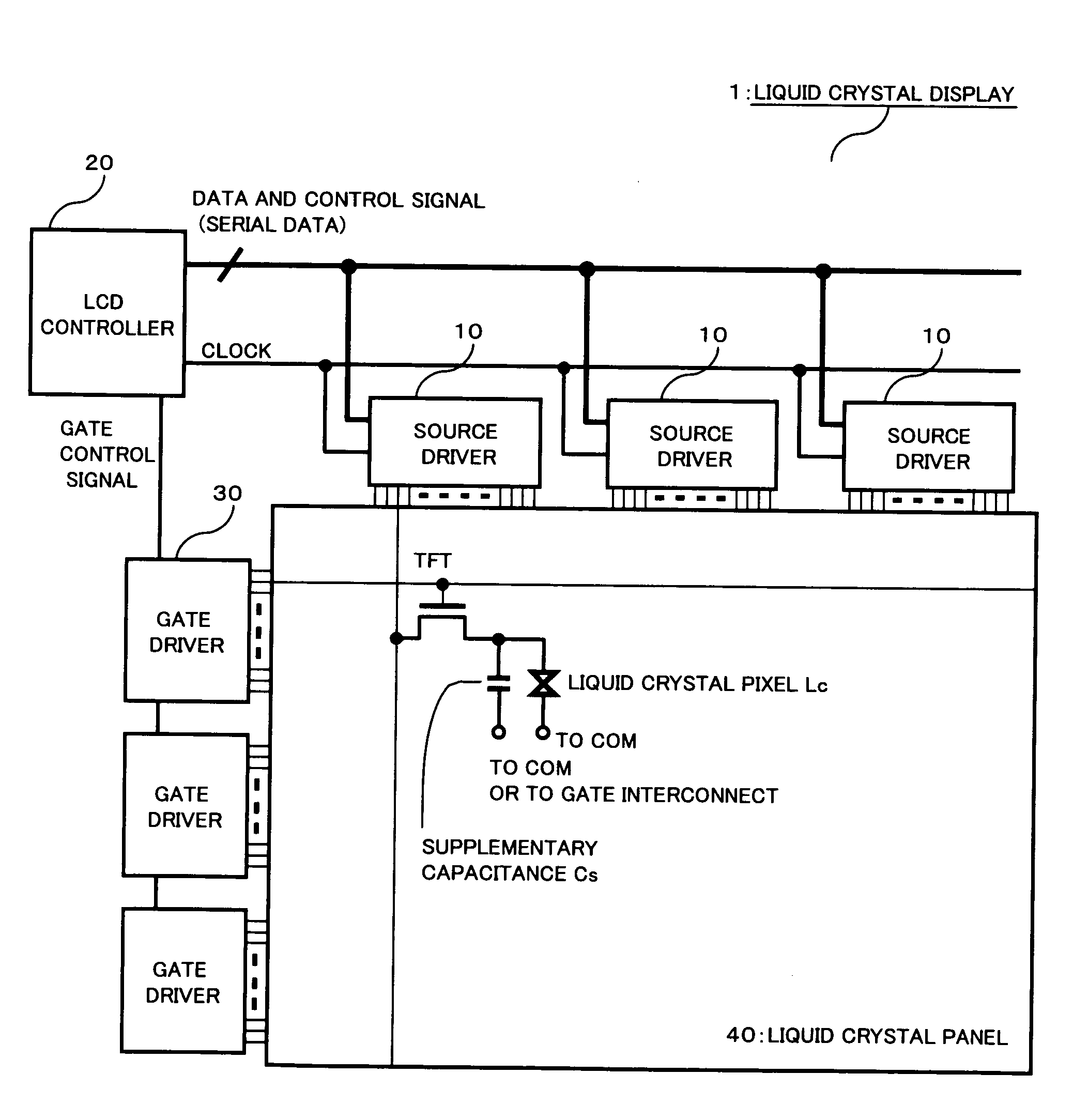
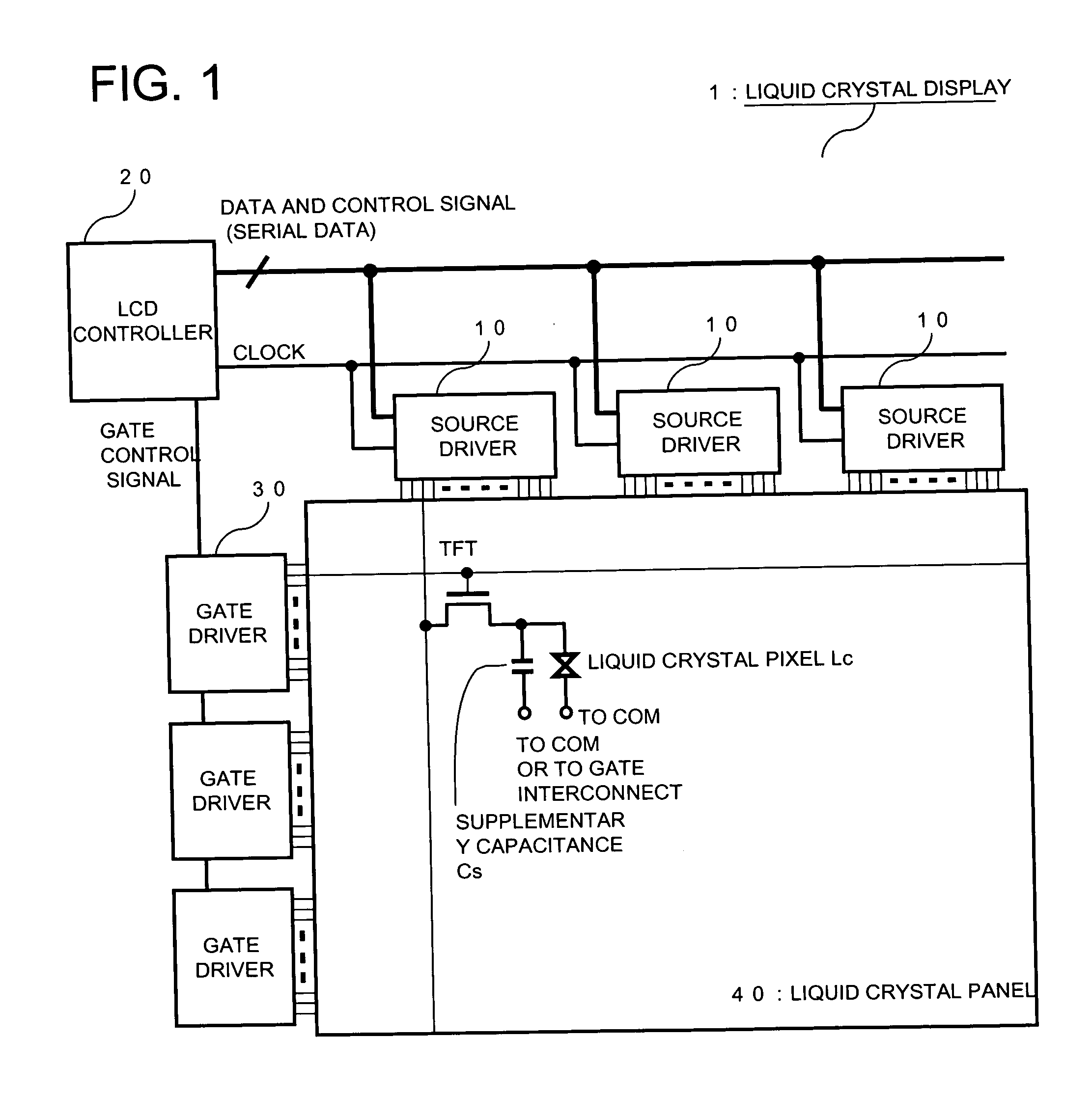
[0037]FIG. 1 shows a formulation of a liquid crystal display according to Example 1 of the present invention. Referring to FIG. 1, a liquid crystal display 1 includes a plurality of source drivers 10, a timing controller (LCD controller) 20, a plurality of gate drivers 30 and a liquid crystal display panel 40. It is observed that each source driver 10 comprises a source side liquid crystal driver IC and each gate driver comprises a gate side liquid crystal driver IC.

[0038]The LCD controller 20 sends a clock and serial data, composed of data (video data) and a control signal, to the source driver 10, while sending a gate control signal to the gate drivers 30, respectively. Each thin-film transistor TFT, provided within the liquid crystal display panel 40, has a source driven by the associated source driver 10, while having a gate driven by the associated gate driver 30. The drain of each TFT is connected via a liquid crystal pixel (liquid crystal part) Lc and a supplementary capacita...

example 2

[0054]FIG. 6 shows a formulation of a source driver in Example 2 of the present invention. The source driver shown in FIG. 6 differs from the source driver of Example 1 in that some of the gray scale voltages, which are VDATA255(+), VDATA128(+), VDATA0(+), VDATA128(−) and VDATA255(−) in the present Example, are delivered to an output switch impedance control circuit 16A. Using these input multiple gray scale voltages, the output switch impedance control circuit 16A generates a stepped waveform within the output switch impedance controlling time to control the impedance of the output switching circuit 17 stepwise.

[0055]FIG. 7 shows the relationship among the power supply voltage, a common voltage and the gray-scale potentials in a normally black type liquid crystal display, in which the common voltage (VCOM) is fixed.

[0056]FIG. 8 depicts a circuit diagram of an output switch impedance control circuit according to Example 2 of the present invention. The output switch impedance control...


PUM


Abstract

A liquid crystal display in which it is possible to reduce the EMI noise ascribable to high harmonic contents in a charging / discharging current is disclosed. The liquid crystal display includes a source driver 10. The source driver includes output terminals (OUTn) that drive a liquid crystal panel, amplifiers 15 that amplify a video signal and output switching circuits 17 each connected between an output of the amplifier 15 and the output terminal. The source driver also includes an output switch impedance control circuit 16 that controls the switching operation of the output switching circuits 17. When turned on during the operation of switching the output switching circuit 17, the output switch impedance control circuit 16 exercises control to progressively lower the impedance of the output switching circuit 17.

Description

REFERENCE TO RELATED APPLICATION[0001]This application is based upon and claims the benefit of the priority of Japanese patent application No. 2008-156782, filed on Jun. 16, 2008, the disclosure of which is incorporated herein in its entirety by reference thereto.TECHNICAL FIELD[0002]This invention relates to a driving circuit and a display. More particularly, it relates to a driving circuit adapted to reduce the EMI (Electro-Magnetic Interference) and to a display making use of such circuit.BACKGROUND[0003]A liquid crystal display (LCD) is used in a wide range of application, such as office automation (OA), domestic appliances or industrial appliances, as a flat panel display indispensable for the era of information communication, in order to take advantage of its thin thickness, light weight and low power usage. In general, a liquid crystal driving IC (liquid crystal driving circuit) including a gray scale potential generation circuit, a decoding circuit, an amplifier and so forth...

Claims


Application Information

Patent Timeline
Patent Type & Authority Applications(United States)
IPC IPC(8): G06F3/038G09G3/36
CPCG09G3/3614G09G3/3648G09G3/3688G09G2330/06G09G2310/027G09G2310/066G09G2330/025G09G3/3696
Inventor UMEDA, KENGO
Owner RENESAS ELECTRONICS CORP
Why Eureka
Try Eureka