
Single-pass, heavy ion fusion, systems and method

Inactive Publication Date: 2009-12-17
ARCATA SYST
View PDF5 Cites 22 Cited by
  • Summary
  • Abstract
  • Description
  • Claims
  • Application Information

AI Technical Summary

Benefits of technology

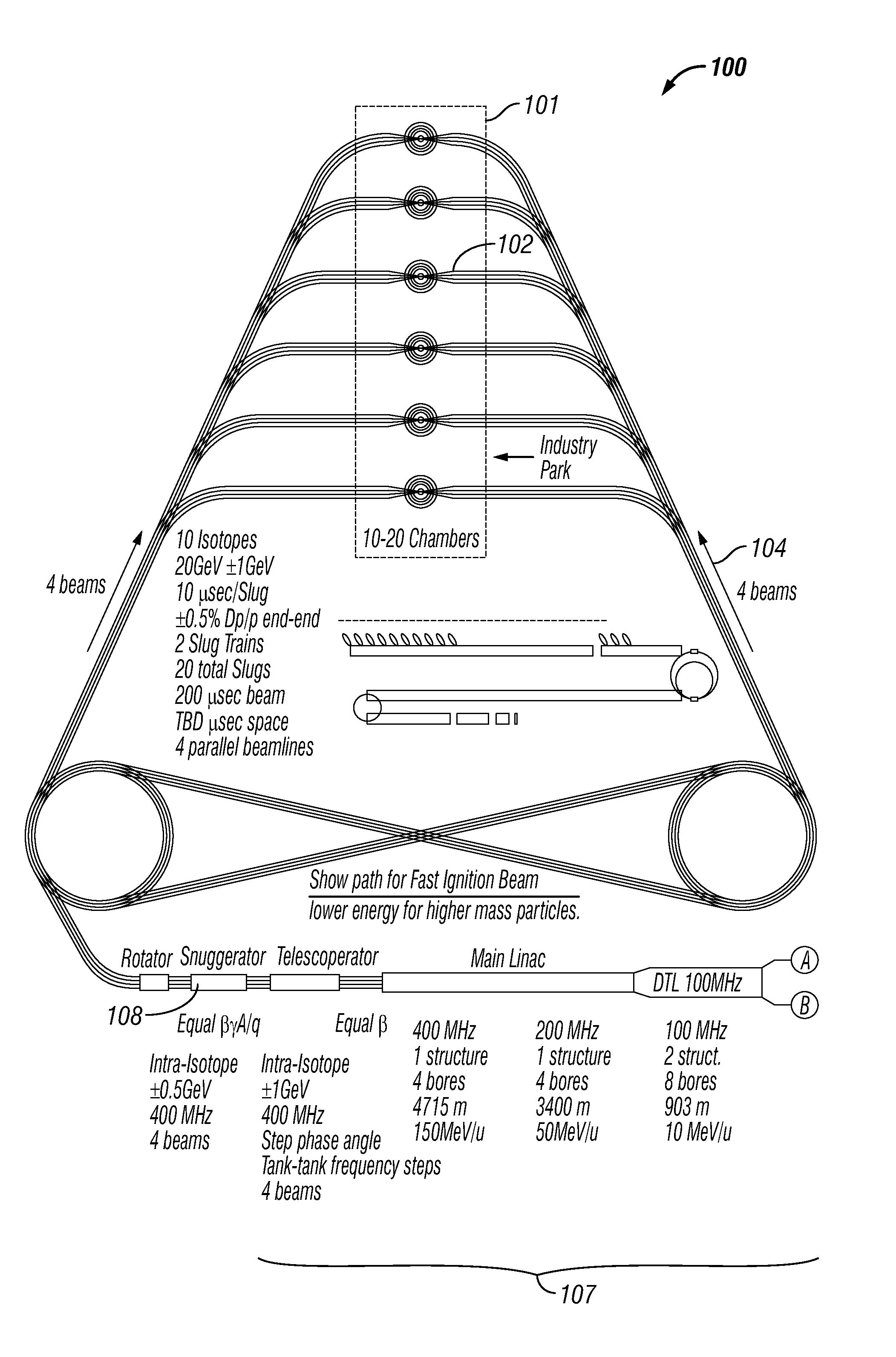
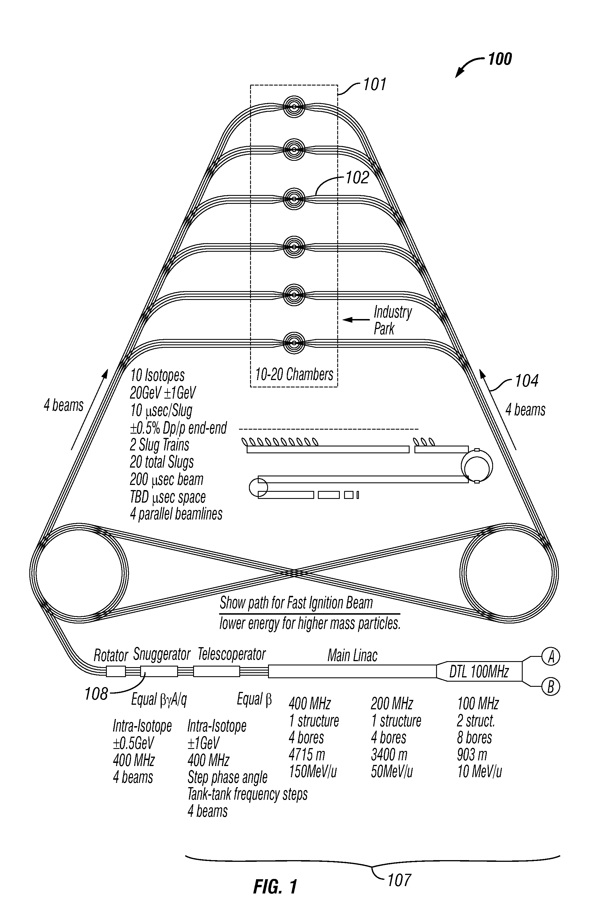
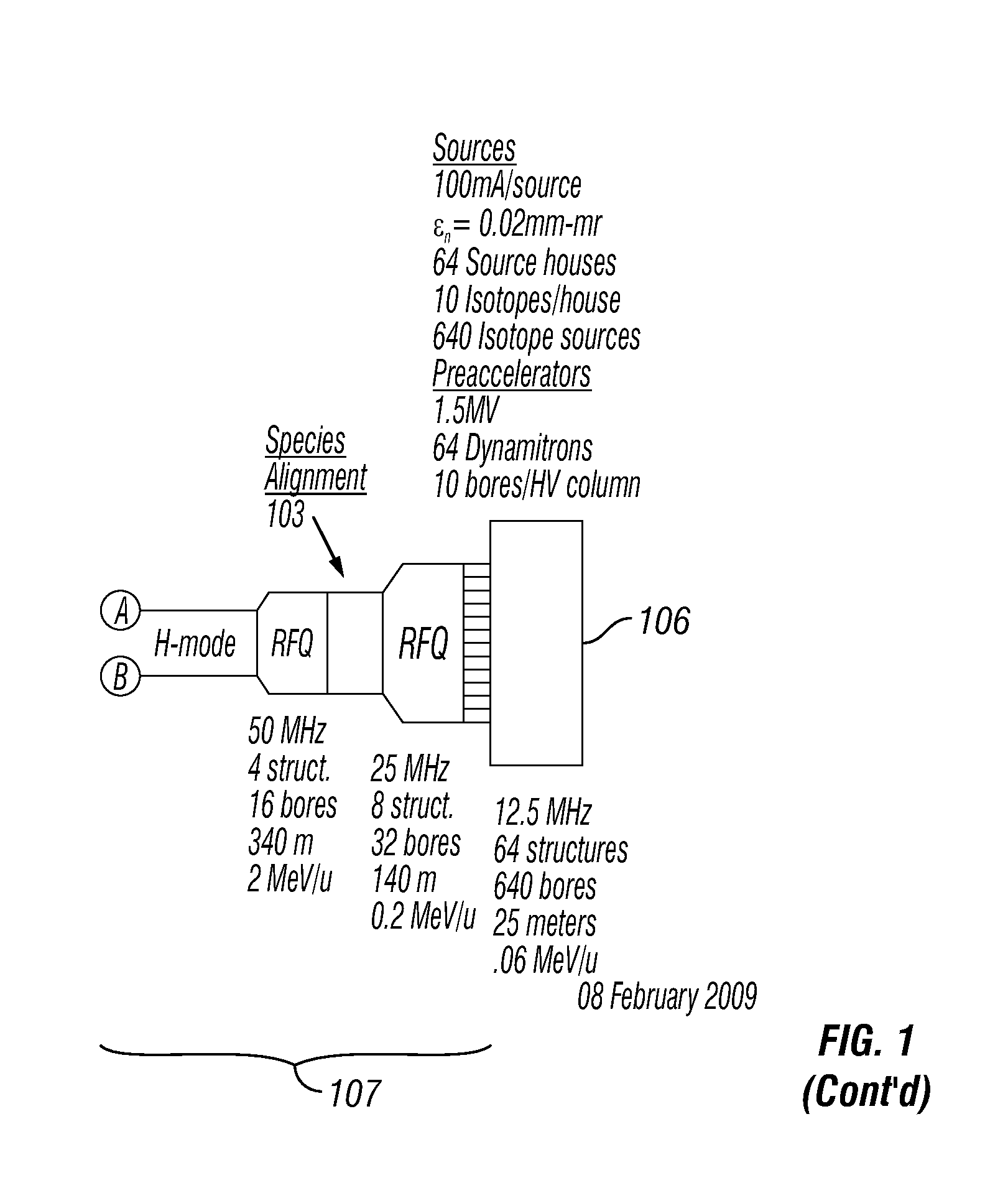
[0019]A single-pass heavy-ion fusion system includes a new arrangement of current multiplying processes that employs multiple isotopes to achieve the desired effect of distributing the task of amplifying the current among all the various processes, to relieve stress on any one process, and to increase margin of safety for assured ICF (inertial confinement fusion) power production. Energy and power of the ignition-driver pulses are greatly increased, thus increasing intensity of target heating and rendering reliable ignition readily attainable. The present design eliminates the need for storage rings. Further innovations are to give the HIF (heavy ion fusion) Driver flexibility to drive multiple chambers in the most general case of different total distances between the linac output and each of the various chambers. Using multiple chambers steeply decreases the pro-rata capital investment and operating costs per power production unit, in turn decreasing the cost of power to users.

Problems solved by technology

However, the need to generate an ignition pulse within a limited time places a constraint on the accelerator technology that eliminates slow pulsing machines like synchrotrons.
However, the potential ways to use this additional design factor to best advantage were not aggressively explored, and only formally adopted in an internationally vetted “point” design in 1995-97.
Using multiple chambers steeply decreases the pro-rata capital investment and operating costs per power production unit, in turn decreasing the cost of power to users.

Method used


Image

  • Single-pass, heavy ion fusion, systems and method
  • Single-pass, heavy ion fusion, systems and method
  • Single-pass, heavy ion fusion, systems and method

Examples


Embodiment Construction

[0047]A single-pass heavy-ion fusion system includes a new arrangement of current multiplying processes that employs multiple isotopes to achieve the desired effect of distributing the task of amplifying the current among all the various processes, to relieve stress on any one process, and to increase margin of safety for assured ICF (inertial confinement fusion) power production. Energy and power of the ignition-driver pulses are greatly increased, thus increasing intensity of target heating and rendering reliable ignition readily attainable. The present design eliminates the need for storage rings. Further innovations are to give the HIF (heavy ion fusion) Driver flexibility to drive multiple chambers in the most general case of different total distances between the linac output and each of the various chambers. Using multiple chambers steeply decreases the pro-rata capital investment and operating costs per power production unit, in turn decreasing the cost of power to users.

The ...


PUM


Abstract

A single-pass heavy-ion fusion system includes a new arrangement of current multiplying processes that employs multiple isotopes to achieve the desired effect of distributing the task of amplifying the current among all the various processes, to relieve stress on any one process, and to increase margin of safety for assured ICF (inertial confinement fusion) power production. Energy and power of the ignition-driver pulses are greatly increased, thus increasing intensity of target heating and rendering reliable ignition readily attainable. The present design eliminates the need for storage rings. Further innovations are to give the HIF (heavy ion fusion) Driver flexibility to drive multiple chambers in the most general case of different total distances between the linac output and each of the various chambers. Using multiple chambers steeply decreases the pro-rata capital investment and operating costs per power production unit, in turn decreasing the cost of power to users.

Description

CROSS-REFERENCE TO RELATED APPLICATIONS[0001]This application claims benefit of U.S. provisional patent application Ser. No. 61 / 061,593, filed Jun. 13, 2008, titled “Heavy Ion Fusion” (attorney docket no. ARCA0002PR), the entirety of which is incorporated herein by this reference thereto.BACKGROUND OF THE INVENTION[0002]1. Field of the Invention[0003]In a general sense, the invention is related to fusion power systems. More particular the invention is related to single-pass, heavy ion fusion, system and methods.[0004]2. Background Information[0005]The heavy ion driver defined in 1975 by R. L. Martin and A. W. Maschke used the known abilities of high-energy RF (radiofrequency) accelerator systems to store megajoule quantities of ion beam energy and to focus this stored energy on very small spots. They saw that the short stopping distance of nuclei with high atomic number (Z) at one-half the speed of light meant being able to create the energy density in small targets containing fusio...

Claims


Application Information

Patent Timeline
IPC IPC(8): G21B1/00
CPCG21B1/03G21B1/15Y02E30/16Y02E30/14H05H1/22H05H7/06Y02E30/10
Inventor BURKE, ROBERT J.BURKE, ALEXANDER THOMAS
Owner ARCATA SYST
Learn More