Multi-stage piston compressor

a piston compressor and multi-stage technology, applied in the direction of piston pumps, positive displacement liquid engines, machines/engines, etc., can solve the problem of problems such as the application of piston compressors

Inactive Publication Date: 2009-12-17
BORSIG COMPRESSOR PARTS GMBH
View PDF13 Cites 14 Cited by
  • Summary
  • Abstract
  • Description
  • Claims
  • Application Information

AI Technical Summary

Benefits of technology

[0003]It is therefore an object of the invention to improve a multi-stage piston compressor, to the extent that the pressure and volume flow may be varied in a simple manner with one and the same machine.
[0006]One may set the multi-stage piston compressor to different delivery powers and pressures in a flexible manner due to the fact that one forgoes the mechanical movement coupling of the individual pistons. Thus, for example, the speed of the pistons may be varied, if a reduced volume flow is desired. Thereby, the stroke and speed of all pistons does not need to be increased or reduced to the same extent, but rather it is possible due to the inventive independent control of the drives, to vary the stroke and the speed of the individual pistons of the different stages independently of one another. In particular, it is possible to change the displacement volume by changing the stroke, for example of the second stage, in dependence on the pressure increase, which takes place in the first stage.
[0007]Preferably, the control device is thus designed in a manner such that the stage pressure ratio of the piston-cylinder unit may be changed by the individual control of the linear drives of the at least two piston-cylinder units. This is not possible with conventional piston compressors, which have a common crank shaft driving all pistons, since the pressure ratio and the volume ratio between the individual stages are matched to one another in a fixed manner. According to the invention, it is possible to change the stage pressure ratios of the individual stages by the mechanically independent drives of the nearest piston-cylinder units and the associated individual control. If the stage pressure ratio of a preceding stage, for example of the first stage, is increased, then accordingly, the displacement volume may be adapted by reducing the stroke in the subsequent stage, i.e., for example of the second stage. The stage pressure ratio thereby may likewise be changed by changing the stroke. Thereby, it is simultaneously possible to adapt the rates of stroke such that the individual stages, i.e. the individual piston-cylinder units, operate at the same frequency, even with a different stroke. Moreover, the dead space in the cylinder may be reduced, i.e. the volumetric losses may be reduced, by the individual control of the drives, since the upper and lower dead point may be moved to in a precise manner by the linear drive and the more precise control.
[0010]Further preferably, the piston-cylinder units are designed in a dry-running manner. Thus, one may forego lubrication on operation, which significantly simplifies the complete construction of the compressor, and permits an application where a lubricant contamination of the gas to be compressed must be avoided.
[0013]According to a particular embodiment of the invention, a switch-over valve is arranged on the exit side of at least a first piston-cylinder unit, by which valve the exit-side flow path may be switched between a subsequent second piston-cylinder unit and an exit conduit, preferably an exit conduit for several piston-cylinder units. This switch-over valve may also be actuated via the control device or, however, may be manually actuatable. Such a switch-over valve permits the piston compressor according to the invention to be converted from a multi-stage operation into a multi-flow operation, in which the individual piston-cylinder units of the several stages are not arranged in series, but are operated connected in parallel. Such an application may then be preferred if a larger volume flow is desired, with a lower pressure ratio between the entry pressure and the exit pressure of the compressor. It may also be possible, depending on the number of stages or piston-cylinder units in the piston compressor, not to connect all piston-cylinder units in parallel, but only individual ones. Moreover, by the use of such a switch-over valve, it is also possible to completely switch off individual piston-cylinder units. Thus, for example, with a three-stage piston compressor, the switch-over valve, which is arranged on the exit side of the second stage, i.e. of the second piston-cylinder unit, may be switched over such that the flow path no longer leads to the third piston-cylinder unit, but the flow is deflected directly into the exit conduit of the piston compressor. Then, for the thus separated or disconnected piston-cylinder unit, the linear drive is not set into operation at all by the control device. The efficiency of the compressor in such an operating mode may be increased in this manner, since the power loss may be reduced.

Problems solved by technology

For this reason, it is problematic to apply such piston compressors where different compressions or pressures and different volume flows are to be realized with one and the same machine.

Method used


Image

  • Multi-stage piston compressor
  • Multi-stage piston compressor
  • Multi-stage piston compressor

Examples


Embodiment Construction

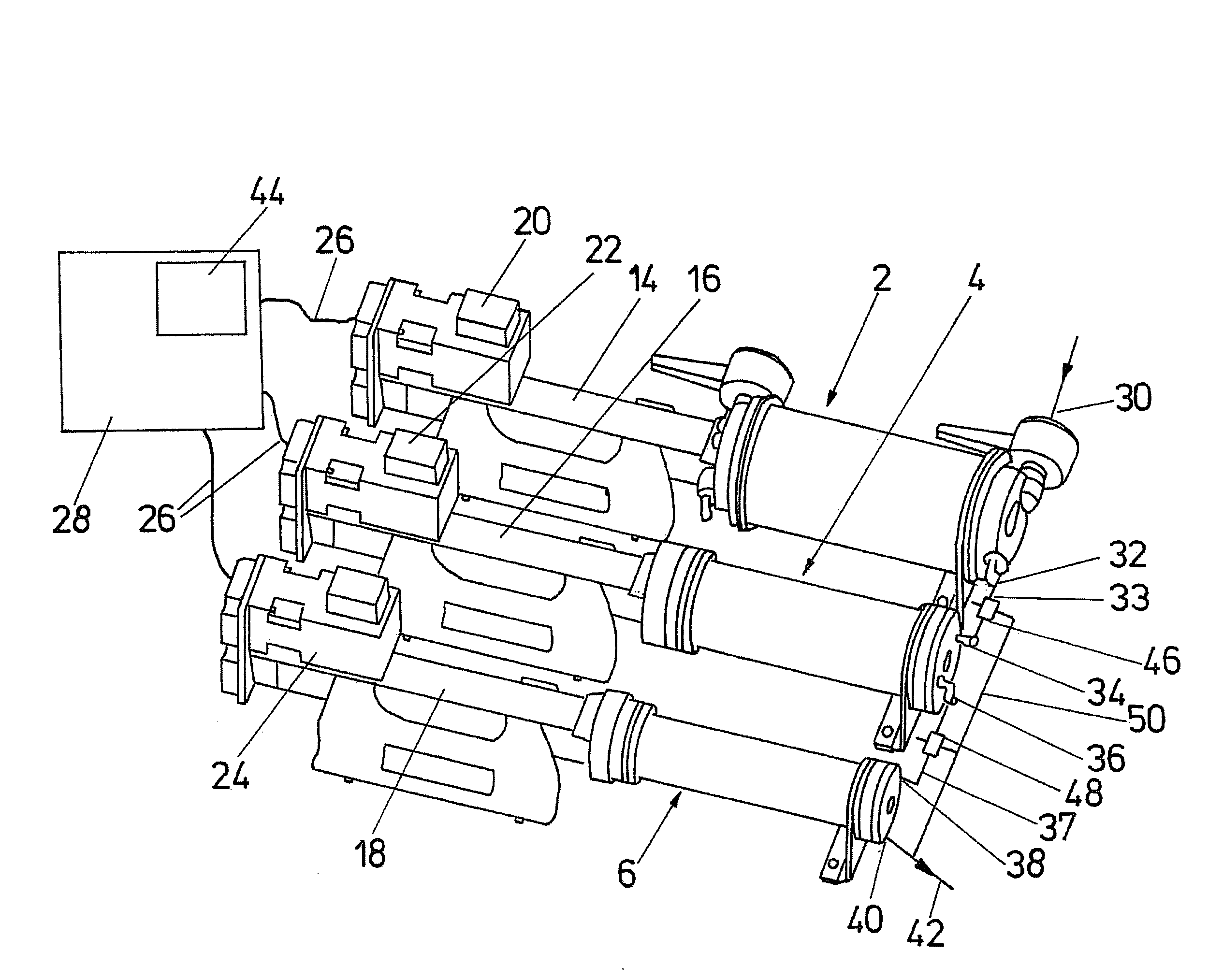
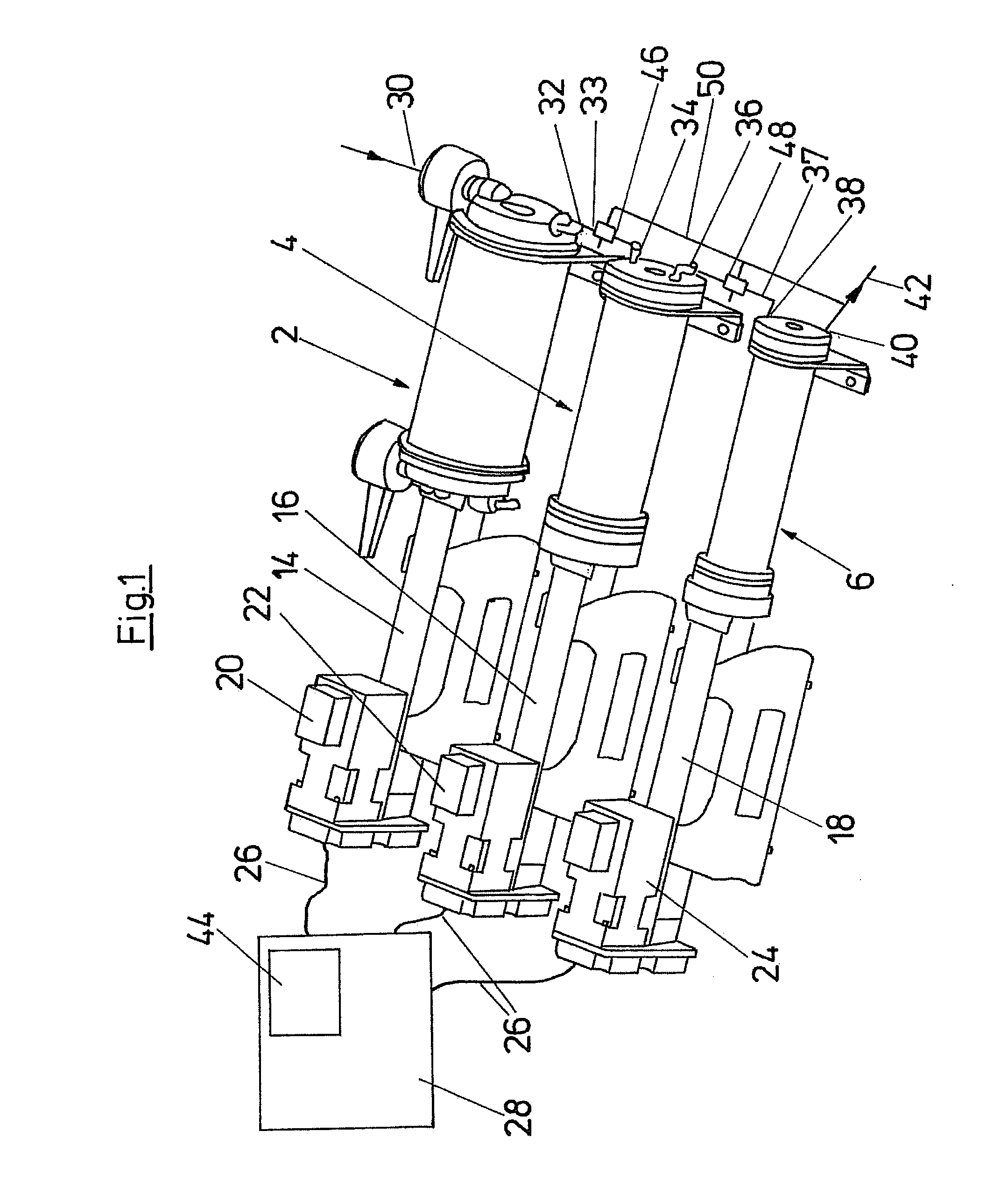
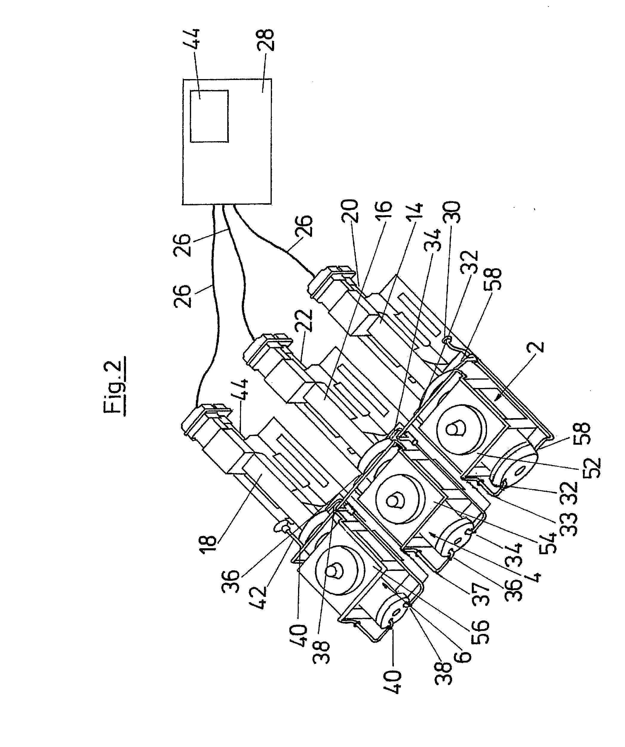
[0020]The piston compressor shown in FIG. 1 is designed in a three-stage manner and accordingly comprises three piston-cylinder units 2, 4 and 6. The piston-cylinder units 2, 4, 6, as is shown in FIG. 4, consist in each case of a cylinder 8 which is cylindrical in cross section and of a piston 10 which is linearly movable therein. The piston 10 is connected to a piston rod 12. The cylinder 8 in a known manner comprises inlet valves and outlet valves, which may be designed as spring-biased check valves, which are suitably connected to the entry conduits and exit conduits.

[0021]According to the invention, each piston-cylinder unit 2, 4, 6 has its own linear drive 14, 16, 18. The piston-cylinder unit 2 comprises a linear drive 14 which is connected to the piston rod 12 of the piston cylinder unit 2, in order to move its piston 10 linearly in the inside of the cylinder 8. Correspondingly, the piston-cylinder unit 4 is connected to its own linear drive 16, which moves the piston 10 of th...


PUM


Abstract

A multi-stage piston compressor is provided with at least two piston-cylinder units, which respectively comprise a separate linear drive for moving the piston. A control device is also provided, which is designed in a manner such that the linear drives may be controlled individually with regard to speed and stroke.

Description

BACKGROUND OF THE INVENTION[0001]The invention relates to a multi-stage piston compressor having at least two piston-cylinder units.[0002]Multi-stage piston compressors are known, in order to increase the pressure of a gas in several stages. With such multi-stage compressors, the exit pressure is increased in a first stage to a first intermediate pressure by a first piston-cylinder unit. This first intermediate pressure is then increased to a yet higher pressure in the second stage by a second piston-cylinder unit. This continues in accordance with the number of applied stages. With the known piston compressors, the pistons of all piston-cylinder units are driven via a common crank drive, which fixedly sets the stroke of the piston. Moreover, the diameter of the individual cylinders is selected differently, depending on the pressure ratio between the individual stages, i.e. the inner diameter of the cylinders reduces from stage to stage, since the volume of the gas decreases with ea...

Claims


Application Information

Patent Timeline
Patent Type & Authority Applications(United States)
IPC IPC(8): F04B25/00
CPCF04B9/02F04B35/01F04B25/02F04B25/00
Inventor SCHULZ, HARALDTITTEL, ROLAND
Owner BORSIG COMPRESSOR PARTS GMBH
Why Eureka
Try Eureka