Device for distributing the coolant in an air-conditioning system of a motor vehicle

a technology for air-conditioning systems and motor vehicles, which is applied in the direction of refrigeration components, transportation and packaging, light and heating apparatus, etc., can solve the problems of not solving the above described problems

Active Publication Date: 2018-10-04
HANON SYST
View PDF3 Cites 6 Cited by
  • Summary
  • Abstract
  • Description
  • Claims
  • Application Information

AI Technical Summary

Problems solved by technology

However, this system cannot sol

Method used


Image

  • Device for distributing the coolant in an air-conditioning system of a motor vehicle
  • Device for distributing the coolant in an air-conditioning system of a motor vehicle
  • Device for distributing the coolant in an air-conditioning system of a motor vehicle

Examples


first embodiment

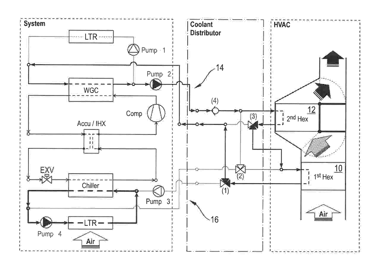
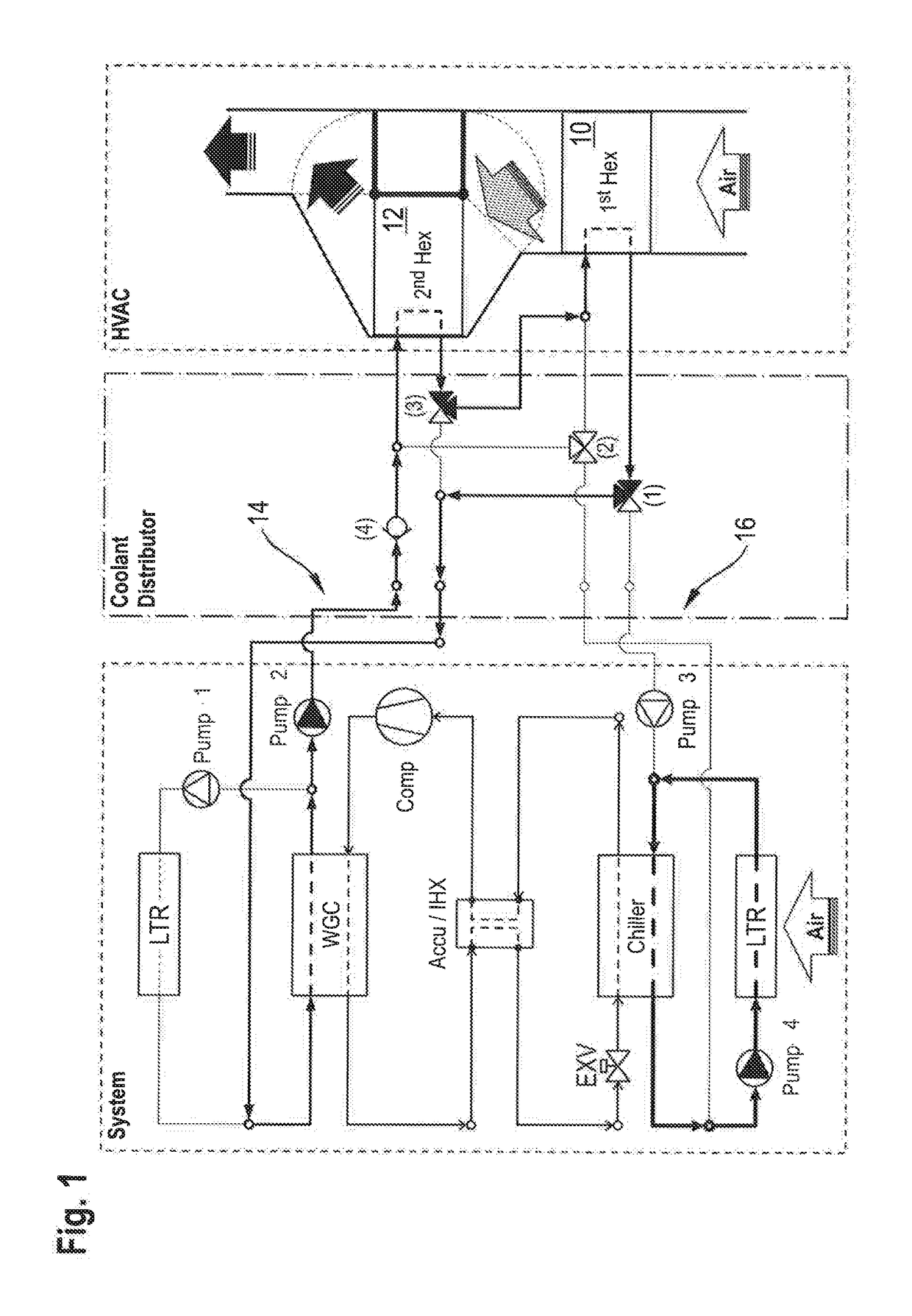
[0025]FIG. 1 the heat pump system according to the invention during heating,

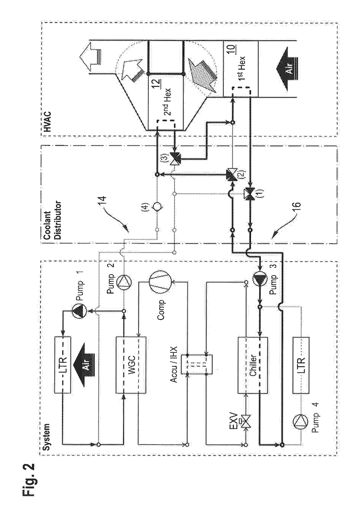
[0026]FIG. 2 the first embodiment of the heat pump system according to the invention during cooling,

[0027]FIG. 3 the first embodiment of the heat pump system according to the invention during dehumidifying,

second embodiment

[0028]FIG. 4 the heat pump system according to the invention during heating,

[0029]FIG. 5 the second embodiment of the heat pump according to the invention during cooling,

[0030]FIG. 6 the second embodiment of the heat pump system according to the invention during dehumidifying,

third embodiment

[0031]FIG. 7 the heat pump system according to the invention during heating,

[0032]FIG. 8 the third embodiment of the heat pump system according to the invention during cooling,

[0033]FIG. 9 the third embodiment of the heat pump system according to the invention during dehumidifying.


PUM


Abstract

A heat pump system for a motor vehicle comprises at least two heat exchangers 10, 12, through which, for heating and/or cooling the motor vehicle interior, a flow is conducted, and at least two coolant circulations 14, 16 separable from one another, of which at least one is connectable, independently of the other coolant circulation, with one, two or more heat exchangers 10, 12 such that through these, in the presence of a connection with two or more heat exchangers 10, 12, a flow is successively conducted and the other coolant circulation is connectable with at least one heat exchanger 10, 12.

Description

FIELD OF TECHNOLOGY[0001]The invention relates to a device for the distribution of coolant in a motor vehicle, with at least two coolant circulations as well as one refrigerant circulation. The coolant circulation, developed for the combined operation in chiller mode, heat pump mode and post-heating mode, comprises two coolant-air heat exchangers. To condition the incoming air of the passenger compartment, the temperature level of the coolant in the coolant-air heat exchangers is provided by a refrigerant circulation. The refrigerant circulation typically comprises at least one compressor, an expansion element for relieving the refrigerant from a high to a lower pressure level, a refrigerant-coolant heat exchanger operable as condenser / gas cooler as well as a refrigerant-coolant heat exchanger, operable as evaporator, for the heat transfer between the refrigerant of the refrigerant circulation and the coolant of the coolant circulation.[0002]Depending on the ambient temperature, the...

Claims


Application Information

Patent Timeline
IPC IPC(8): B60H1/00
CPCB60H1/00907B60H1/00885B60H2001/00928B60H2001/00942B60H1/00899F25B25/005F25B40/00F25B2339/047F25B9/008B60H1/32284B60H1/3233
Inventor SPIES, TONIDURRANI, NAVIDKOZALLA, PHILIPP
Owner HANON SYST
Why Eureka
Try Eureka