Premix burner for a gas turbine combustion chamber

a gas turbine and combustion chamber technology, applied in the direction of combustion types, lighting and heating apparatus, combustion using lump and pulverulent fuel, etc., can solve the problems of unstable flame, affecting the affecting the nox emission and quenching limit of the burner, so as to improve the stability of flame, reduce the risk of explosion, and improve the effect of combustion stability

Active Publication Date: 2009-07-28
ANSALDO ENERGIA SWITZERLAND AG
View PDF14 Cites 6 Cited by
  • Summary
  • Abstract
  • Description
  • Claims
  • Application Information

AI Technical Summary

Benefits of technology

[0008]A possibility for reducing these disadvantageous effects is to feed all the required quantity of fuel via the central lance. The burner is then operated at very high air ratios as a diffusion burner. On the one hand, a very high flame stability, but, on the other hand, also very high NOx emissions, result from this.
[0009]A further development of the burner which is discussed above is the subject of EP 1 292 795, which discloses a burner which, even during changes of load or changes of fuel quality, can be stably operated with approximately constantly low emission values. This premix burner includes a housing, which has one or more shells, a mixer chamber, into which combustion air is injected via tangentially arranged slots and which changes into a swirled flow in the mixer chamber, and means for introducing fuel into the combustion air flow, wherein this means has a first group of fuel outlet orifices for a first fuel, which are basically oriented parallel to the burner axis, and at least one second group of fuel outlet orifices for a second fuel, which are basically oriented parallel to the burner axis, wherein the first and the second group are subjectable to fuel admission independently of each other, and the means is preferably arranged in the region of the combustion air inlet slots.
[0010]For further increasing of the flame stability, pilot fuel can be additionally introduced via a lance.
[0011]Since the burner can be exclusively operated with liquid fuel, the possibility arises of maintaining or repairing the gaseous fuel feed device without the operation of the burner or of the combustion chamber having to be completely interrupted for this purpose. This is advantageous for the efficiency of the gas turbine which is equipped with it. As already mentioned elsewhere, however, injection of liquid fuel into the mixer chamber of the burner or into the combustion space of the combustion chamber, as the case may be, customarily leads to appreciably increased flame temperatures, which, for example, is to be ascribed to inadequate atomization, mixing and evaporation of the liquid fuel before its ignition. Increased flame temperatures, however, are associated with a disproportionally increased production of NOx emissions and soot. This disadvantage can be minimized somewhat by water, or water vapor, being admixed with the liquid fuel, for example in a quantity ratio of 1:1, and, instead of liquid fuel, a fuel / water emulsion consequently being injected into the mixer chamber, which leads to a delay of the combustion reaction and to a lowering of the local flame temperatures. In this case, it is again disadvantageous that the feed of such a thinning medium increases the heat transfer in the turbine on the hot gas side, which is accompanied by a reduction of the service life of the turbine. Furthermore, there are sites for power plants in which water is too expensive to be used as a thinning medium. Furthermore, the comparatively short time in which the burner is actually operated with liquid fuel is taken into account, so during a service of the gaseous fuel feed device, or in pilot mode, the costs for preparation of the water, for example dimineralization plants have to be made available for this, are therefore too high.SUMMARY
[0012]One of numerous aspects of the present invention is based on an improved embodiment for a generic type burner, which is especially comparatively cost-effectively realizable and at the same time enables a reduction of NOx emissions and also of soot formation.
[0013]For operation of the generic type burner with liquid fuel, yet another aspect of the present invention involves injecting liquid fuel into the mixer chamber via a plurality of injection orifices which, with regard to a main outflow direction of the burner, are arranged in series, and which inject the liquid fuel with a main injection direction which has a radial component which extends radially to the main outflow direction, wherein a direction which has the oxidator(oxidizer)-fuel mixture, which flows from the mixer chamber, at the outlet opening of the mixer chamber is to be understood by the main outflow direction of the burner. By this type of construction, the injection of liquid fuel is distributed to a plurality of injection orifices, as a result of which the volumetric flow at the individual injection orifice is reduced. In this way, the atomization action of the individual injection orifices can be improved. At the same time, an improved mixing and also an improved evaporation of the liquid fuel ensues as a result. It inevitably results from the arrangement of the injection orifices in series and parallel to the main outflow direction that some of the injection orifices are relatively far from the outlet opening of the mixer chamber. The liquid fuel which is injected there, therefore, has an increased retention time in the mixer chamber, which is favorable to the mixing through and evaporation of the fuel. Furthermore, the radial component of the main injection direction at the respective injection orifice is especially advantageous for the mixing through and evaporation. This measure, then, intensifies the mixing through and evaporation of the liquid fuel.

Problems solved by technology

However, these variables significantly influence the NOx emissions and the quenching limit of the burner, and also its stability with regard to combustion pulsations.
The partial load range is problematical during operation of premix burners, especially such burners in connection with gas turbine plants, since in this case only comparatively low quantities of fuel are added to the combustion air.
With complete mixing of the fuel with all the combustion air, however, a mixture results which even in the low partial load range is no longer ignitable, or only forms a very unstable flame.
This leads to unwanted combustion pulsations or to a possible quenching of the flame.
On the one hand, a very high flame stability, but, on the other hand, also very high NOx emissions, result from this.
As already mentioned elsewhere, however, injection of liquid fuel into the mixer chamber of the burner or into the combustion space of the combustion chamber, as the case may be, customarily leads to appreciably increased flame temperatures, which, for example, is to be ascribed to inadequate atomization, mixing and evaporation of the liquid fuel before its ignition.
Increased flame temperatures, however, are associated with a disproportionally increased production of NOx emissions and soot.
This disadvantage can be minimized somewhat by water, or water vapor, being admixed with the liquid fuel, for example in a quantity ratio of 1:1, and, instead of liquid fuel, a fuel / water emulsion consequently being injected into the mixer chamber, which leads to a delay of the combustion reaction and to a lowering of the local flame temperatures.
In this case, it is again disadvantageous that the feed of such a thinning medium increases the heat transfer in the turbine on the hot gas side, which is accompanied by a reduction of the service life of the turbine.
Furthermore, there are sites for power plants in which water is too expensive to be used as a thinning medium.
Furthermore, the comparatively short time in which the burner is actually operated with liquid fuel is taken into account, so during a service of the gaseous fuel feed device, or in pilot mode, the costs for preparation of the water, for example dimineralization plants have to be made available for this, are therefore too high.
It inevitably results from the arrangement of the injection orifices in series and parallel to the main outflow direction that some of the injection orifices are relatively far from the outlet opening of the mixer chamber.
This injection, in conjunction with the turbulent swirled flow inside the mixer chamber, leads to an intensive mixing through of fuel and oxidator.
The gaseous fuel which is injected at this point, therefore, also has an especially long retention time in the burner, which intensifies the mixing through with the oxidator flow.

Method used


Image

  • Premix burner for a gas turbine combustion chamber
  • Premix burner for a gas turbine combustion chamber
  • Premix burner for a gas turbine combustion chamber

Examples


Embodiment Construction

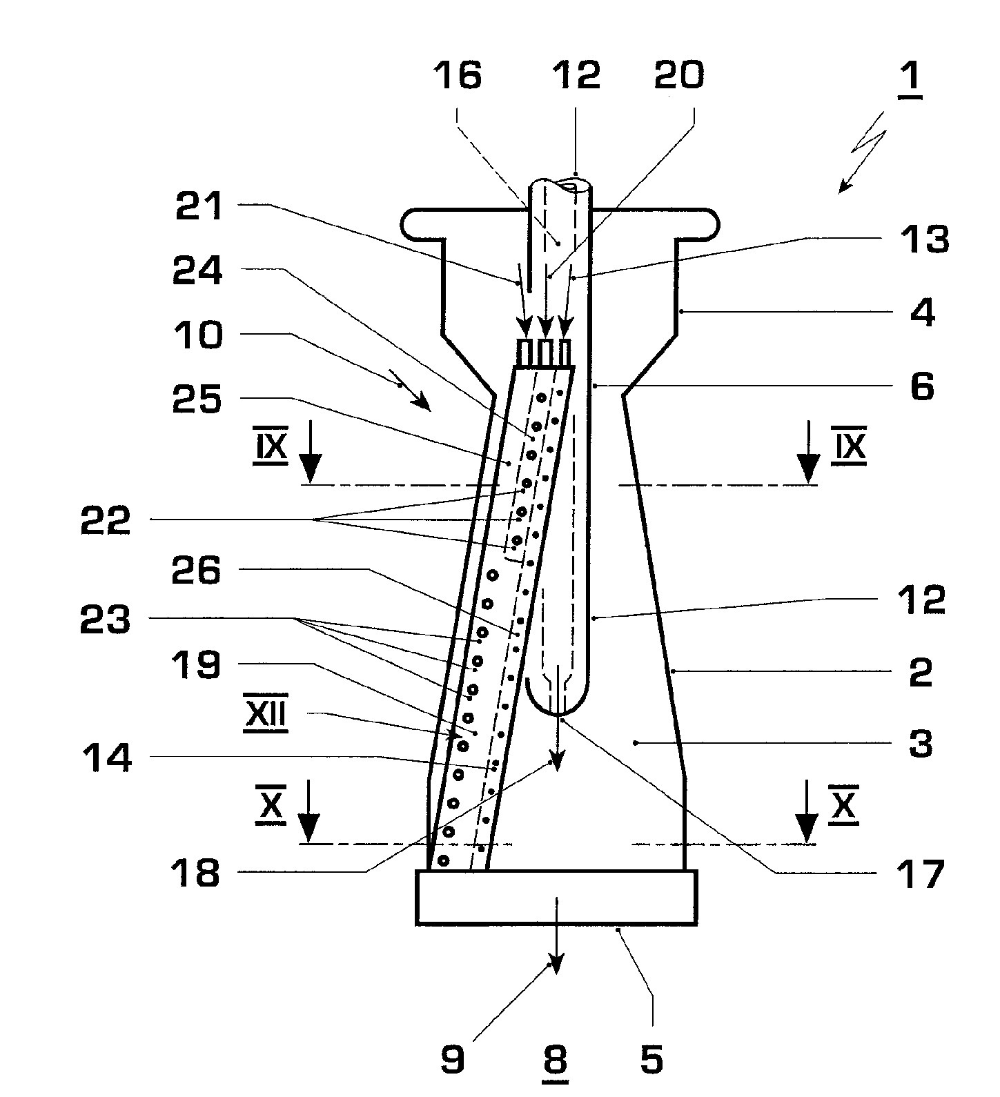
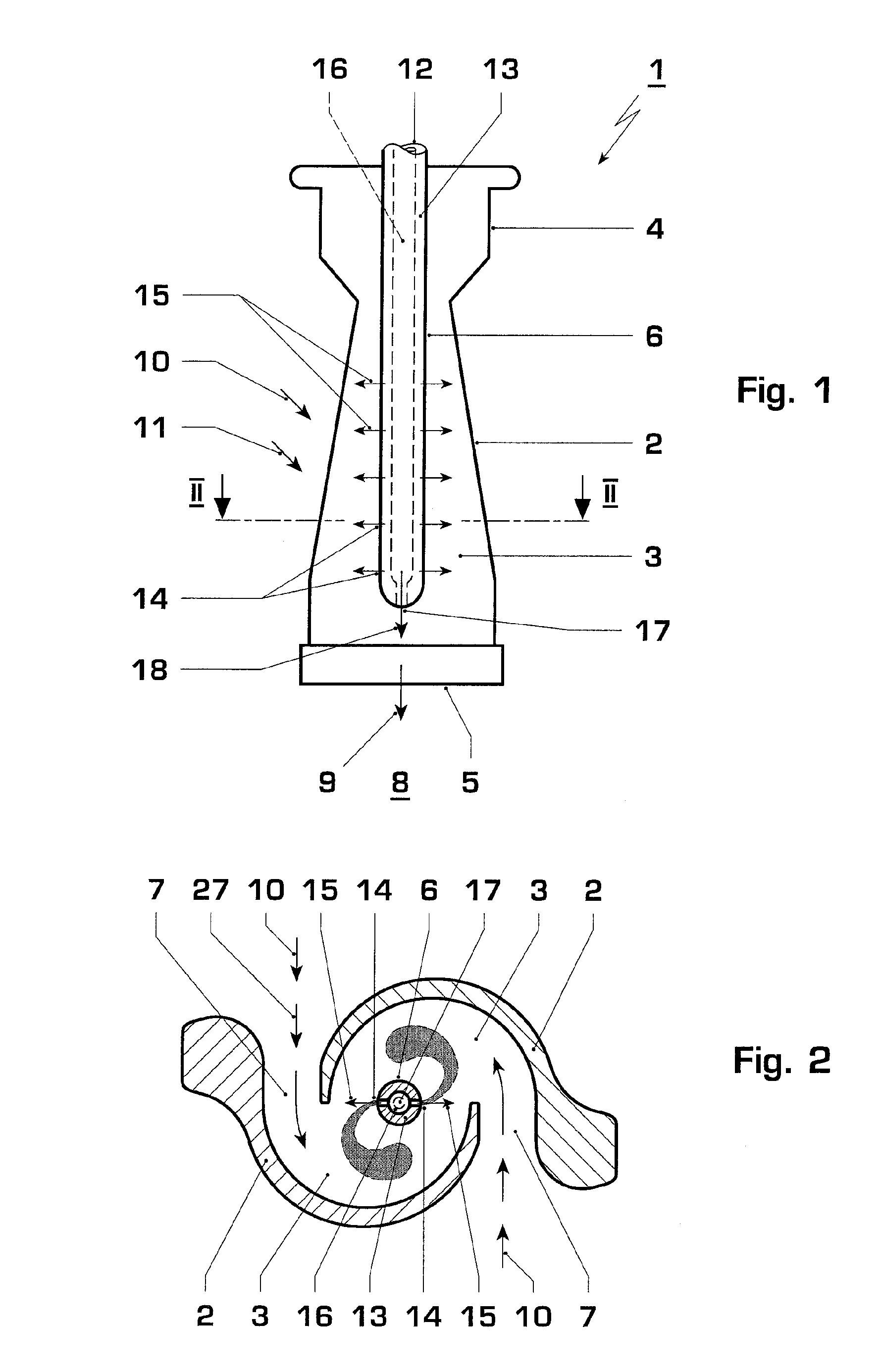
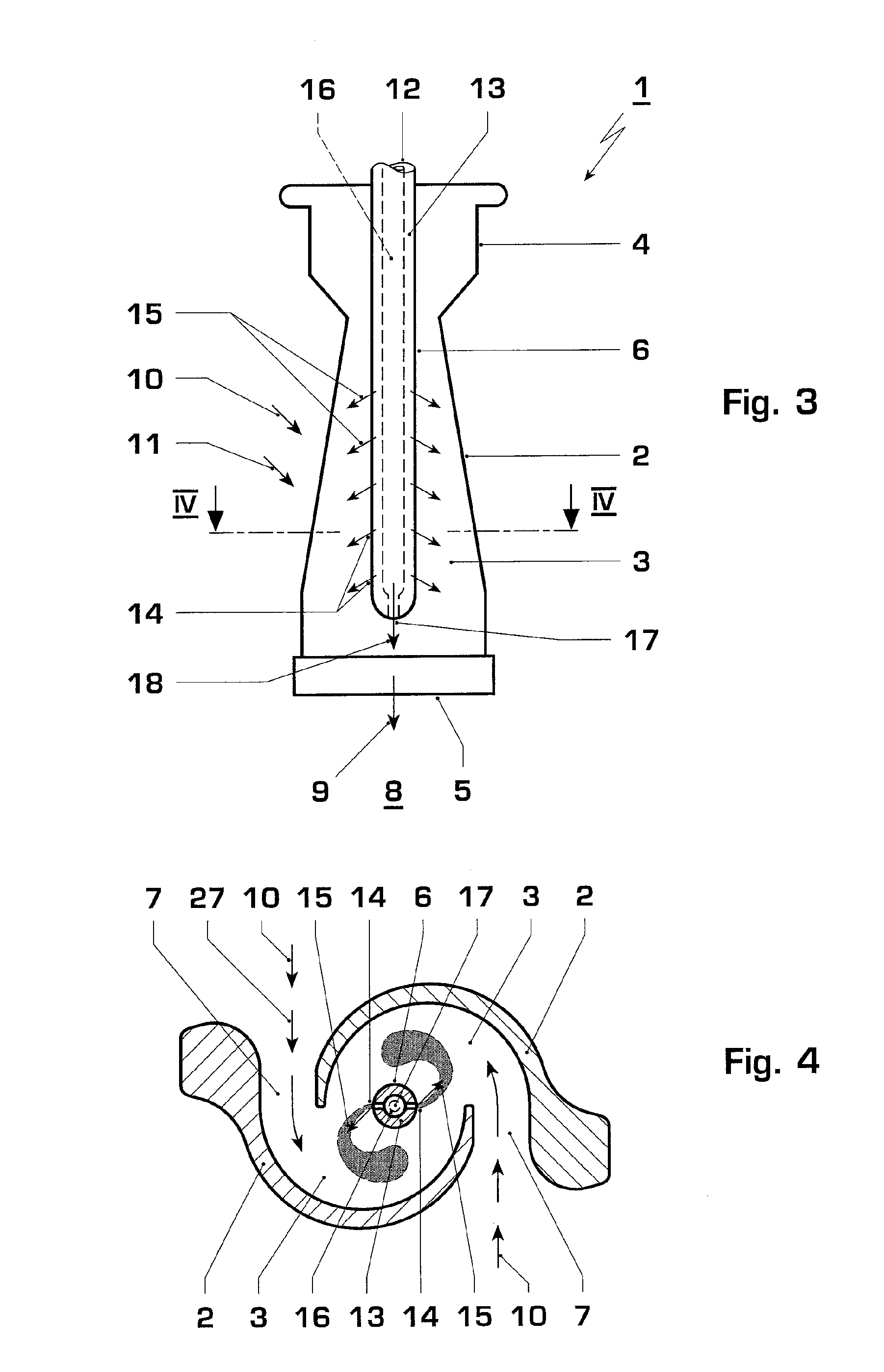
[0035]Corresponding to FIGS. 1, 3, 5, and 8, a burner 1 according to the invention includes a mixer chamber 3 which is defined by a housing 2. Furthermore, the burner 1 has a burner head 4 which is arranged opposite an outlet opening 5 of the mixer chamber 3. In the embodiments which are shown here, a lance 6 is attached to the burner head 4 and projects centrally into the mixer chamber 3. The lance 6 in this case can be arranged on the burner head 4 in a withdrawable or retractable manner, so that to a certain extent it is retracted into the mixer chamber 3 only when required.

[0036]According to FIGS. 2, 4, 6, 7, 9, and 10, the housing 2 in the embodiments which are shown here is designed so that the mixer chamber 3 has two inlet openings 7 for the oxidator. These inlet openings 7 in this case are arranged and designed so that a tangential inflow, and therefore a concentric vortex system, is formed for the mixer chamber 3. This is achieved in this case by a half-shell type of constr...


PUM


Abstract

A burner (1) for a combustion chamber of a gas turbine, especially in a power plant, includes an oxidizer feed device (10) for feeding a gaseous oxidizer into a mixer chamber (3) of the burner (1), a gaseous fuel feed device (11) for feeding a gaseous fuel into the mixer chamber (3), and a liquid fuel feed device (12) for feeding a liquid fuel into the mixer chamber (3). In order to improve the operation of the burner (1) with liquid fuel, the liquid fuel feed device (12) has a main feed line (13) which feeds liquid fuel to a plurality of injection orifices (14). Some of these injection orifices (14), with regard to a main outflow direction (9) of the burner (1), which has an oxidizer-fuel mixture, which flows from the mixer chamber (3), at an outlet opening (5) of the mixer chamber (3), are arranged in series. Some or all of these injection orifices (14) are designed so that a main injection direction (15) of the respective injection orifice (14) has a radial component which extends radially to the main outflow direction (9).

Description

[0001]This application is a Continuation of, and claims priority under 35 U.S.C. § 120 to, International application number PCT / EP2006 / 061144, filed 29 Mar. 2006, and claims priority therethrough under 35 U.S.C. § 119 to German application number No 10 2005 015 152.3, filed 31 Mar. 2005, the entireties of which are incorporated by reference herein.BACKGROUND[0002]1. Field of Endeavor[0003]The invention relates to a premix burner for a combustion chamber of a gas turbine, especially in a power plant, at least having a housing defining a mixer chamber, an oxidator feed device for feeding a gaseous oxidator into the mixer chamber, a gaseous fuel feed device for feeding a gaseous fuel into the mixer chamber, and also a liquid fuel feed device for feeding a liquid fuel into the mixer chamber.[0004]2. Brief Description of the Related Art[0005]A premix burner of the type referred to above is known from EP 0 433 790. The generic type burner has a housing which is built from a plurality of i...

Claims


Application Information

Patent Timeline
Patent Type & Authority Patents(United States)
IPC IPC(8): F23R3/30
CPCF23C7/002F23R3/286F23D17/002
Inventor EROGLU, ADNANTOQAN, MAJED
Owner ANSALDO ENERGIA SWITZERLAND AG
Why Eureka
Try Eureka