Power supply device and vehicle

a power supply device and power supply technology, applied in the direction of electric devices, propulsion parts, propulsion using engine-driven generators, etc., can solve the problems of deterioration of charge/discharge characteristics, difficulty in performing supply/reception of electric power between batteries and capacitors, and reduce capacity, so as to promote effective energy use

Inactive Publication Date: 2009-12-24
TOYOTA JIDOSHA KK
View PDF7 Cites 63 Cited by
  • Summary
  • Abstract
  • Description
  • Claims
  • Application Information

AI Technical Summary

Benefits of technology

[0006]One object of the present invention is to provide a power supply device capable of increasing a temperature of a power storage device to a temperature suitable for an operation of the power storage device, while promoting effective use of energy.
[0021]Therefore, according to the present invention, it becomes possible to increase a temperature of a power storage device included in a power supply device to a temperature suitable for an operation of the power storage device, while promoting effective use of energy.

Problems solved by technology

Generally, in a power storage device such as a secondary battery or a capacitor, a decrease in temperature causes a reduction in capacity, and results in a deterioration in charge / discharge characteristics.
However, unless both the battery and the capacitor have enough states of charge, it is difficult to perform supply / reception of electric power between the battery and the capacitor.
However, since the load consumes electric power just to increase the temperature of the battery in this case, electric power stored in the battery is consumed wastefully.

Method used


Image

  • Power supply device and vehicle
  • Power supply device and vehicle
  • Power supply device and vehicle

Examples


first embodiment

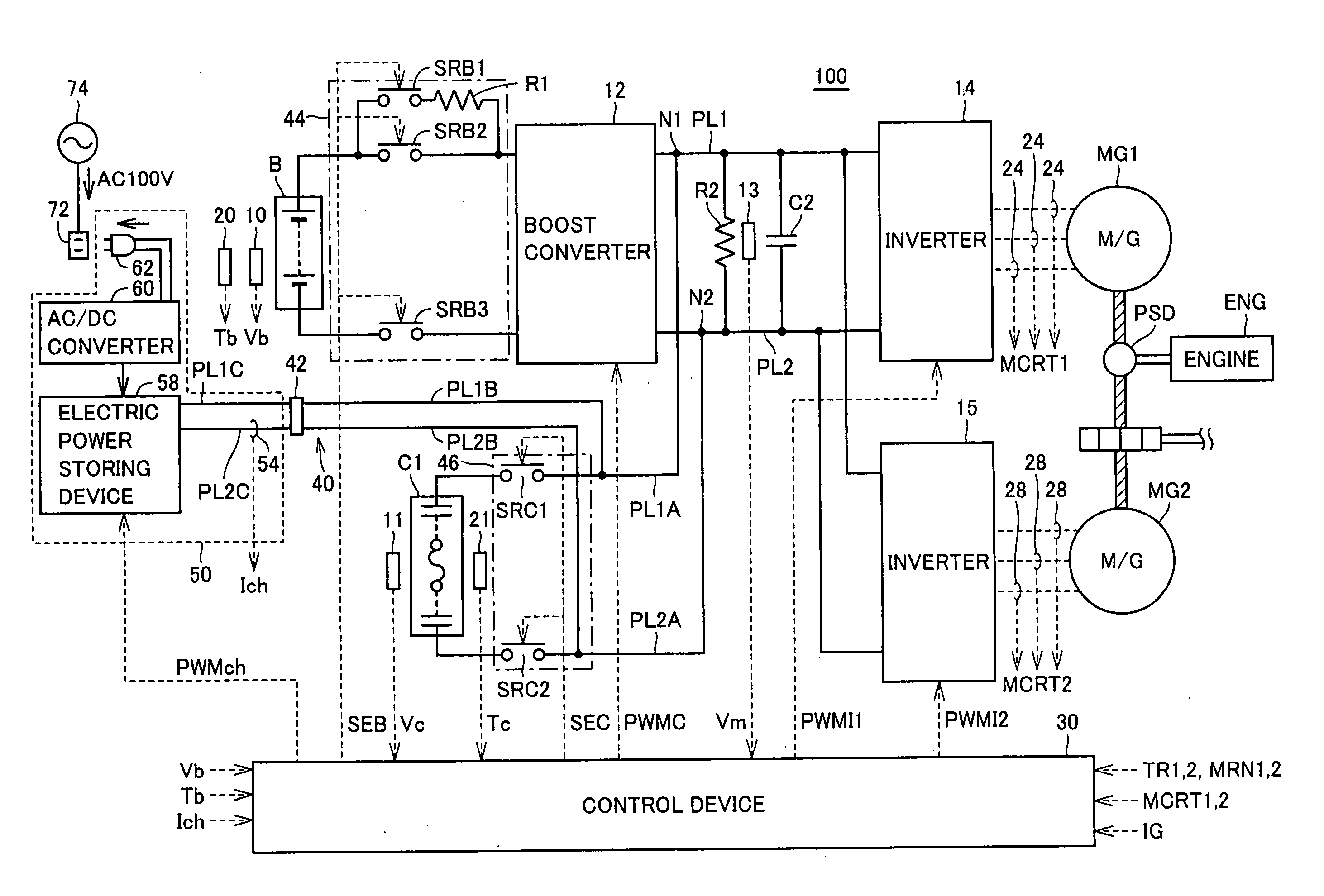
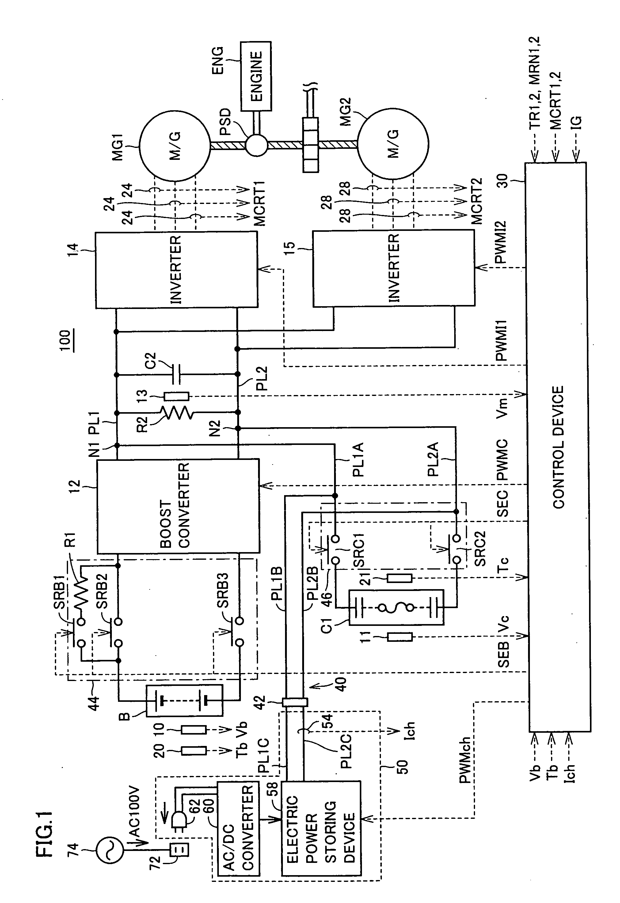
[0034]FIG. 1 is a schematic block diagram of a hybrid vehicle 100 to which a power supply device in accordance with a first embodiment of the present invention is applied.

[0035]Referring to FIG. 1, hybrid vehicle 100 includes a battery B, a boost converter 12, a capacitor C1, a capacitor C2, inverters 14 and 15, voltage sensors 10, 11, and 13, current sensors 24 and 28, temperature sensors 20 and 21, connection units 44 and 46, a resistor R2, and a control device 30.

[0036]An engine ENG generates drive force using combustion energy of a fuel such as gasoline as a source. The drive force generated by engine ENG is split by a power split device PSD into two paths, as indicated by thick diagonal lines in FIG. 1. One is a path transmitting the split drive force to a drive shaft driving wheels via a reduction gear not shown, and the other is a path transmitting the split drive force to a motor generator MG1.

[0037]While motor generators MG1 and MG2 can serve both as an electric power gener...

second embodiment

[0127]A power supply device of a second embodiment has a configuration similar to the power supply device of the first embodiment. However, a charge / discharge device connected to the power supply device in the second embodiment has a configuration different from that of the first embodiment.

[0128]FIG. 9 is a view showing a configuration of a charge / discharge device connected to a power supply device in accordance with a second embodiment of the present invention.

[0129]Referring to FIGS. 9 and 1, a charge / discharge device 50A is different from charge / discharge device 50 in that charge / discharge device 50A further includes a DC / DC converter 64. A solar battery 76 and / or a wind power generation device 78 as an electric power generation device(s) are / is connected to DC / DC converter 64. The electric power generation device is not particularly limited to solar battery 76 or wind power generation device 78, and various types of electric power generation devices can be used.

[0130]DC / DC conv...


PUM

PropertyMeasurementUnit
DC voltageaaaaaaaaaa
electric poweraaaaaaaaaa
voltageaaaaaaaaaa

Abstract

A power supply device mounted to a hybrid vehicle includes: a capacitor that is chargeable / dischargeable; an electric power input / output unit for inputting / outputting electric power between the capacitor and a charge / discharge device installed external to the hybrid vehicle; a temperature sensor detecting a temperature of the capacitor; and a control device increasing the temperature of the capacitor by performing at least one of charging from the charge / discharge device to the capacitor and discharging from the capacitor to the charge / discharge device when the control device determines based on a detection result of the temperature sensor that the temperature of the capacitor is required to be increased. Thereby, the temperature of the capacitor can be increased without causing a load such as an inverter to consume electric power.

Description

TECHNICAL FIELD[0001]The present invention relates to a power supply device and a vehicle. In particular, the present invention relates to a technique increasing the temperature of a power storage device included in a power supply device.BACKGROUND ART[0002]In recent years, considering environmental issues, attention has been paid to hybrid vehicles, electric vehicles, and the like. Such a vehicle is equipped with an electric motor as a motive power source, and equipped with a power storage device such as a secondary battery or a capacitor as an electric power source therefor.[0003]Generally, in a power storage device such as a secondary battery or a capacitor, a decrease in temperature causes a reduction in capacity, and results in a deterioration in charge / discharge characteristics. Therefore, when the temperature of a power storage device decreases after start-up of a vehicle system in a vehicle as described above, it is necessary to increase the temperature of the power storage ...

Claims


Application Information

Patent Timeline
Patent Type & Authority Applications(United States)
IPC IPC(8): H02J7/00B60K6/445B60K6/46B60L9/18B60W10/08B60W10/26B60W20/00H01G9/28H01M10/44H01M10/60
CPCB60K6/445Y02T10/6239B60L8/00B60L8/003B60L11/123B60L11/14B60L11/1816B60L11/1824B60L11/1851B60L11/1861B60L11/1868B60L11/187B60L11/1875B60L2210/20B60L2220/14B60W10/08B60W10/26B60W20/00B60W2510/246H01G9/28H01M10/486H01M10/5006H01M10/5016H01M10/5022H01M10/5097H02J7/1453Y02T10/6217Y02T10/7005Y02T10/7022Y02T10/7044Y02T10/7066Y02T10/7077Y02T10/7083Y02T10/725Y02T90/121Y02T90/127Y02T90/14B60L7/26H01M10/625H01M10/615H01M10/633H01M10/667Y02T10/7072B60L53/14B60L50/61B60L50/16B60L58/10B60L58/20B60L58/24B60L58/27H02J7/007194Y02T10/62Y02T10/70Y02T10/72Y02E60/10B60W2510/244H02J7/14H01M10/44H02J7/00B60W10/24Y02T90/12
Inventor SOMA, TAKAYAMOGARI, TAKESHI
Owner TOYOTA JIDOSHA KK
Why Eureka
Try Eureka