Touch sensor

Inactive Publication Date: 2009-12-24
KONINKLIJKE PHILIPS ELECTRONICS NV
View PDF6 Cites 9 Cited by
  • Summary
  • Abstract
  • Description
  • Claims
  • Application Information

AI Technical Summary

Benefits of technology

[0011]The measures have the effect that the resistive layer needs only to be connected via the single terminal to the detecting device. This has the advantage that the construction of the touch sensor is simplified, and is more flexible with regards to the shape and size of an object on which the touch sensor is to be placed. For example the sensor may be integrated in textile for making a garment, and requires only a single connection from the location of the sensor to the detecting device.
[0012]The invention is also based on the following recognition. The document US 2005/0052429 describes a sensor having resistive elements, which require to be coupled to respective detecting channels at both ends. The position of the finger is detected by comparing the channels at both ends. Balancing the results from both ends is required to suppress disturbances and eliminate the effect of the unknown return capacity. The inventors have seen that it is possible to form a touch sensor by an open-ended pattern having a resistance coupled at one side to a sensitive detecting circuit. Surprisingly the effect of the unknown return capacity from a single detecting channel can be eliminated in the detecting circuit, and the resistance differences between various touch positions along the pattern are detectable with sufficient accuracy.
[0013]In an embodiment of touch sensor the resistive layer is shaped according to the elon

Problems solved by technology

However, providing a number of terminals and corre

Method used


Image

  • Touch sensor
  • Touch sensor
  • Touch sensor

Examples


Embodiment Construction

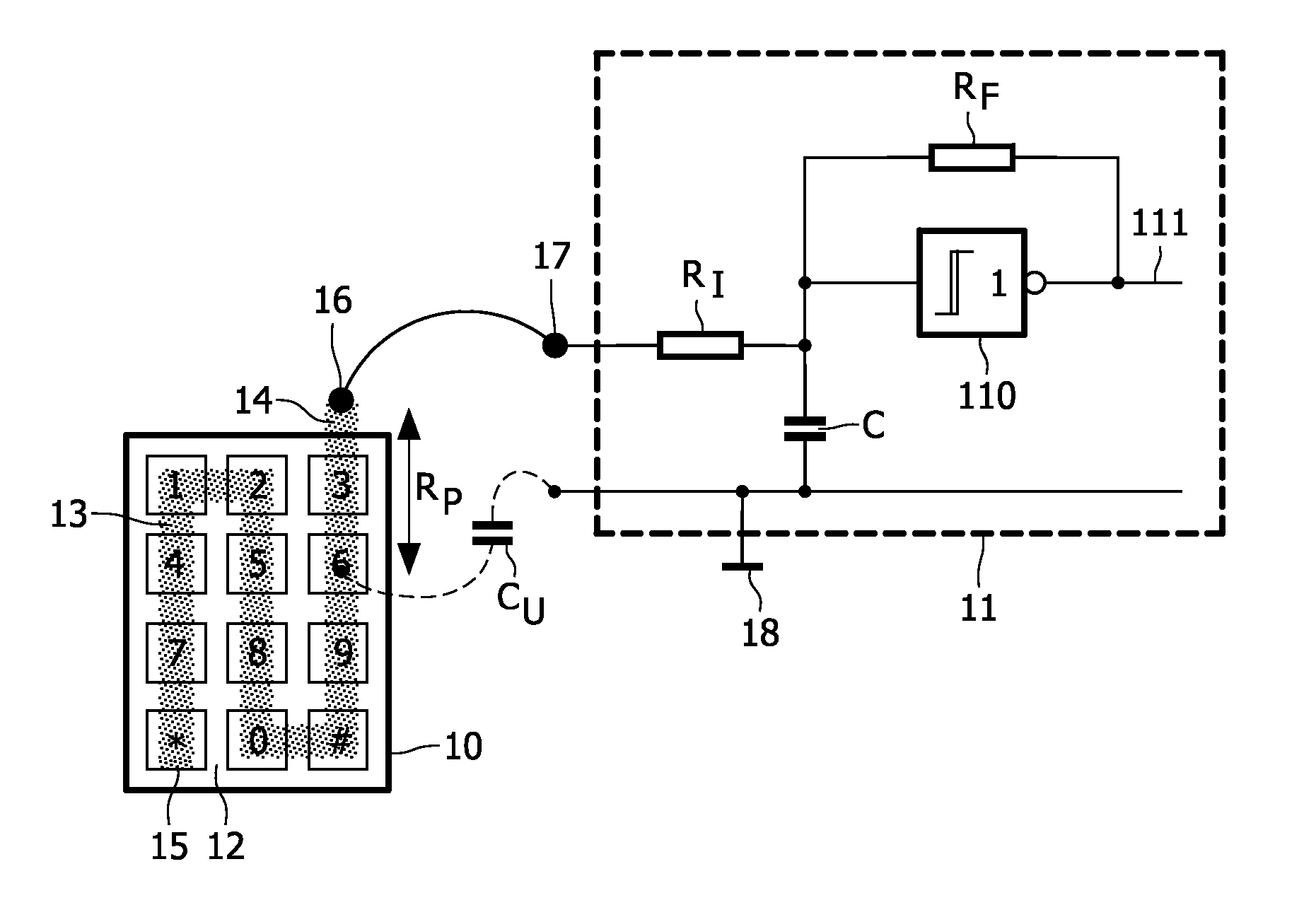
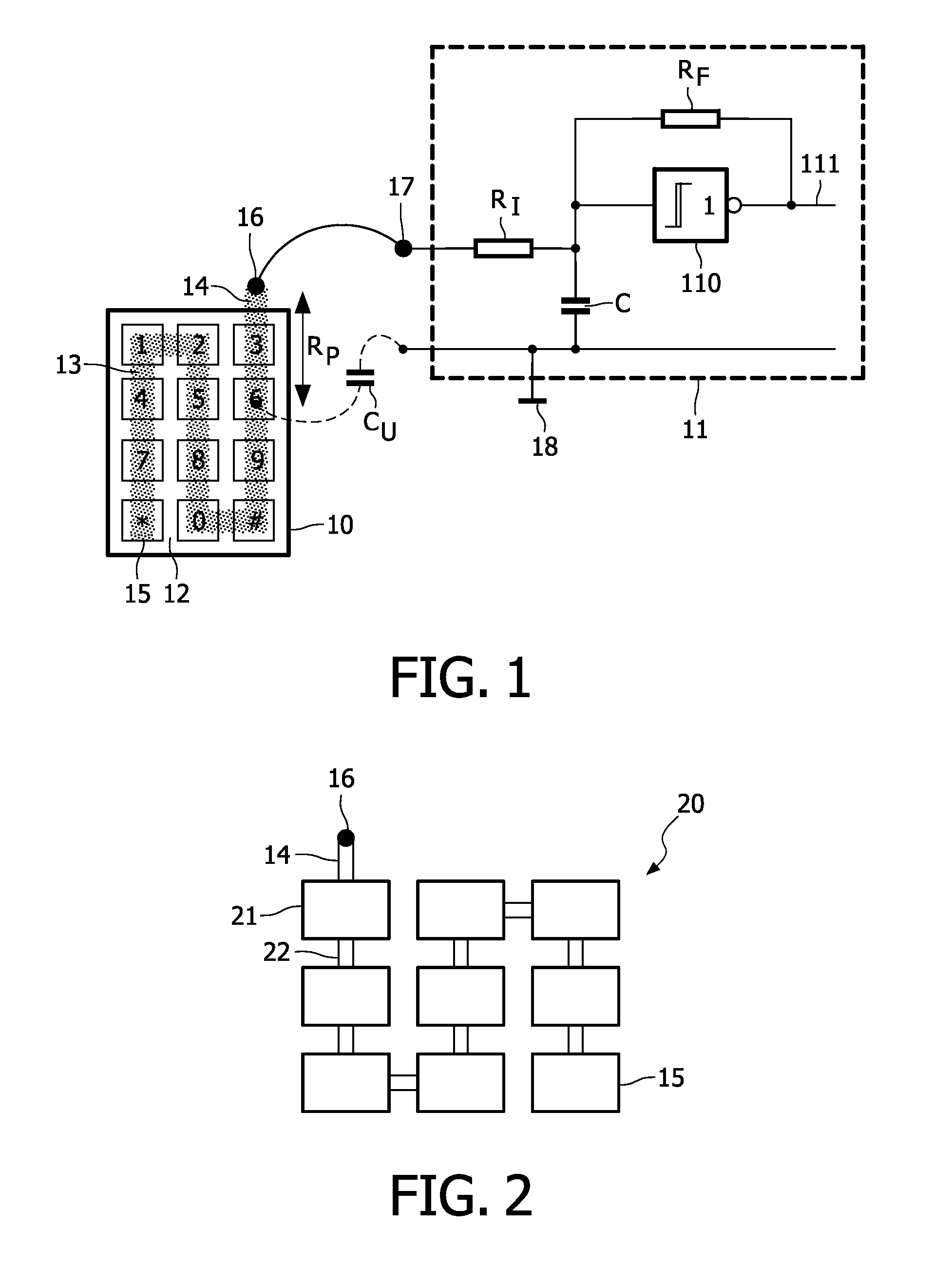
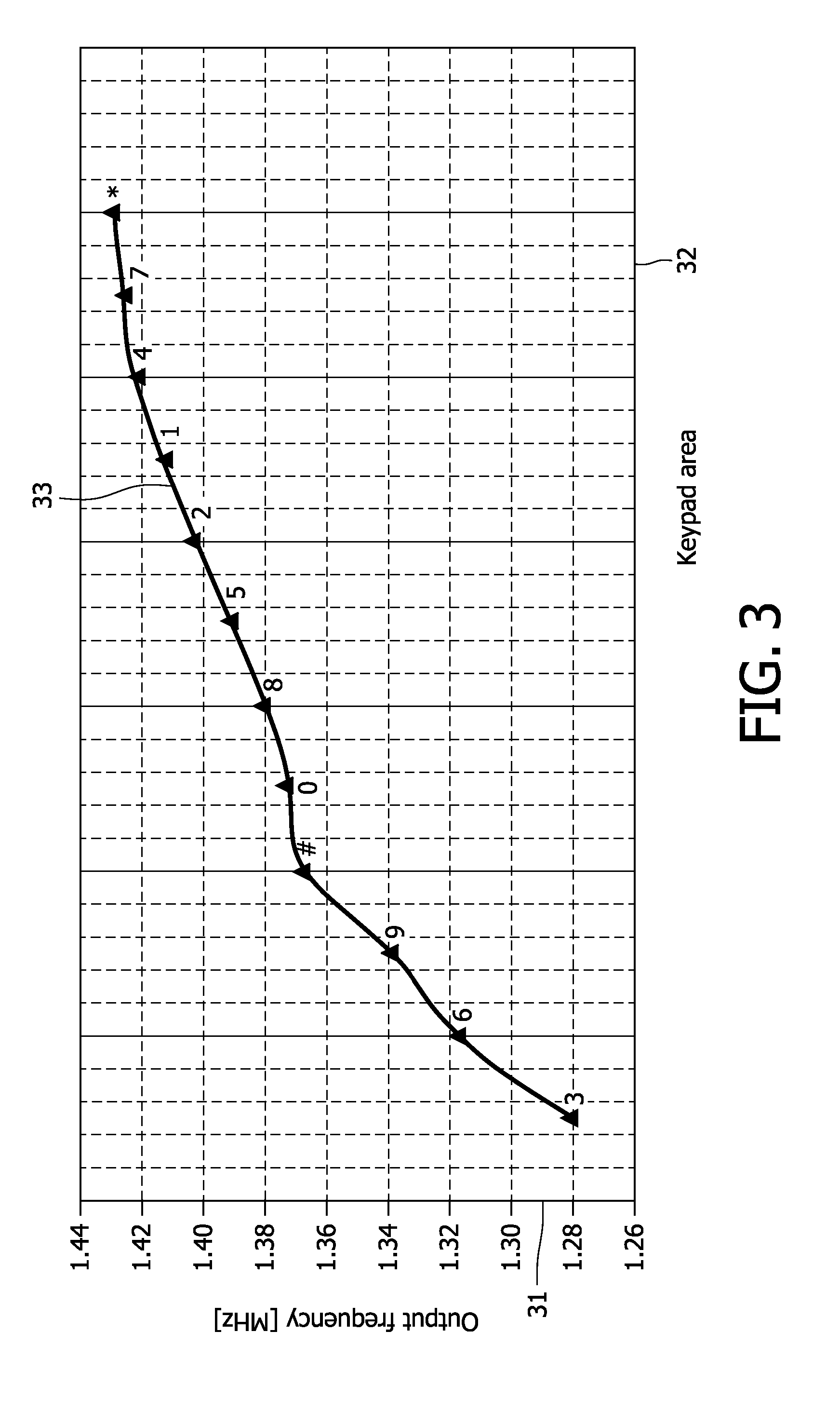
[0026]FIG. 1 shows a touch sensor and a detecting device. The touch sensor 10 has a support layer 12 of an insulating material and a resistive layer 13 applied to the support layer. The resistive layer is formed by a resistive material shaped according to an elongated pattern forming a sequence of touch positions. The Fig. shows a sequence of a numerical keyboard, whereas the elongated pattern has the from of a strip passing along the digits in a predefined order (*, 7, 4, 1, 2, 5, 8, 0, #, 9, 6, 3).

[0027]It is noted that the layout of the keypad shown in the Fig. is not part of the resistive strip. It is a layout provided on the support layer on top of the resistive layer, which visually informs the user of the user interface.

[0028]The strip has, at a connectable end 14 of the sequence, a single terminal 16 arranged to be coupled to a sense input 17 of a detecting device 11. The other end of the strip, called the open end 15 of the sequence opposite to the connectable end of the se...


PUM


Abstract

A touch sensor has a support layer (12) of an insulating material and a resistive layer (13) applied to the support layer. A resistive material is shaped according to an elongated pattern forming a sequence of touch positions, and has a single terminal (16) to be coupled to a sense input (17) of a detecting device (11), while an open end (15) of the sequence opposite to the terminal end remains unconnected. The detecting device detects an active resistance (Rp) between the single terminal and one of said touch positions that is touched by a user via a return capacitance constituted (Cu) by the user and a mass element (18) coupled to the detecting device. Advantageously only a single terminal is necessary, whereas a number of touch positions can be discriminated.

Description

FIELD OF THE INVENTION[0001]The invention relates to a touch sensor comprising a support layer of an insulating material and a resistive layer applied to the support layer.[0002]The invention further relates to a method of manufacturing the touch sensor.[0003]The invention further relates to a detecting device for cooperating with the touch sensor.[0004]The invention relates to the field of sensors to be touched by an object, typically a user's finger, for operating electronic devices. The sensor may be positioned on the surface of an object, e.g. a consumer device, or may be integrated in textile for constituting a wearable user interface to a personal mobile unit.BACKGROUND OF THE INVENTION[0005]The document US 2005 / 0052429 describes a capacitive position sensor for detecting the position of an object, typically an operator's finger, relative to a resistive sensing element. The sensing element comprises a sensing path that has terminals connected along it that subdivide the sensin...

Claims


Application Information

Patent Timeline
IPC IPC(8): G06F3/041
CPCH03K17/9622G06F3/044G06F3/04164G06F3/0443
Inventor ALEXANDER, DOUGLAS ULRICH
Owner KONINKLIJKE PHILIPS ELECTRONICS NV
Why Eureka
Try Eureka