Unlock instant, AI-driven research and patent intelligence for your innovation.

Method for Controlling a Glow Plug in a Diesel Engine

a technology for diesel engines and glow plugs, which is applied in the direction of machines/engines, mechanical equipment, light and heating equipment, etc., can solve the problems of excessive temperature, over-loaded glow plugs, and impaired service li

Active Publication Date: 2009-12-24
BORGWARNER BERU SYST
View PDF8 Cites 17 Cited by
  • Summary
  • Abstract
  • Description
  • Claims
  • Application Information

AI Technical Summary

Benefits of technology

[0016]The invention avoids the difficulties encountered by experts in attempting to control the temperature of a glow plug directly or with the aid of a physical or mathematical model of the glow plug; it does so by not attempting to determine the temperature of the glow plug or any variable of a physical model modeled to the temperature of the glow plug. Instead, the invention determines the time gradient of a temperature-dependent electric variable, present at the glow plug, and compares it with one or more threshold values.
[0017]The gradient of a temperature-dependent measured electric variable can be determined without there being any need to know the absolute temperature value. This simplifies the measuring task quite considerably.
[0020]When the gradient reaches or exceeds a predefined load limit, the load can be reduced immediately by reducing the effective electric voltage supplied to the glow plug.
[0021]In contrast, when the gradient indicates that the temperature rise reflected by it could be steeper without any risk of damage to the glow plug, then the effective electric voltage supplied to the glow plug can be increased even in the current preheating phase so that the ignition temperature and, in consequence thereof, the steady-state temperature of the glow plug can be reached more quickly without any damage to the glow plug, because monitoring of the gradient relative to an upper threshold value prevents excessive loading of the glow plug.
[0023]Relying on the development of the gradient of a temperature-dependent electric variable it is possible to estimate the final temperature that would be reached in case the development of the heating-up process remained without any controlling intervention. Such information can be obtained, for example, by comparing the development in time of the gradient with a reference characteristic representative of the development in time of the gradient that was recorded for a glow plug of the same type under realistic installation conditions. Especially, it is possible to compare the curve of the gradient with the curve of the gradient of a different glow plug, heated up under ideal conditions, and to reduce the effective supply voltage when the observed gradient suggests that an excessive final temperature will be reached, or in contrast to increase the supply voltage temporarily when the observed gradient suggests that the final temperature to be expected will be too low.

Problems solved by technology

While rapid rising of the glow plug temperature is desirable to permit the diesel engine to be started without delay, if possible, it sets the glow plug at a risk of being overloaded and damaged, or of its service life being impaired.
One particular risk is seen in the development of an excessively high temperature, especially due to excessive temperature overshoot in the temperature curve.
Another particular risk results from the unavoidable thermal inertia of the glow plug and from the fact that glow plugs are composed from materials of different thermal inertia, namely from materials of different thermal capacity and different thermal conductivity.
The mechanical stresses encountered in every preheating phase may cause damage to the glow plug and / or may reduce its service life.
However, the resistance of the glow plug is subject to substantial production-related statistical scatter which limits the quality of information of a resistance measurement with respect to the temperature of the glow plug.
In addition, the temperature measurement and the control of the temperature on the basis of that measurement are rendered even more difficult by the short duration of the heating-up phase and the steepness of the temperature rise.
It is a disadvantage of that arrangement that the result cannot possibly be better than the physical model.
In that case, the glow plug is still warm, and the energy applied to it may not be as high as in the case of a cold start because otherwise the glow plug would get excessively hot and might be damaged.

Method used


Image

  • Method for Controlling a Glow Plug in a Diesel Engine
  • Method for Controlling a Glow Plug in a Diesel Engine
  • Method for Controlling a Glow Plug in a Diesel Engine

Examples


Embodiment Construction

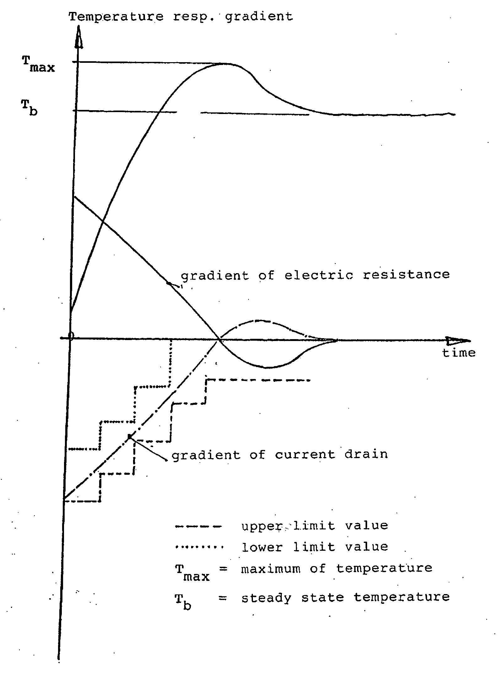
[0028]According to the invention, useful information on the development of the heating process of a glow plug is derived from the time gradient of a temperature-dependent measured electric variable. In order to determine the electric variable that depends on the temperature one may observe the electric resistance of a glow plug and determine its gradient. The resistance can be determined by measuring the voltage available in the on-board system, combined with an independent power measurement. Preferably, one takes into account in this case the voltage drop occurring in the supply line to the glow plug in order to obtain a measuring result which, instead of relying on the resistance of the supply line, substantially only depends on the resistance of the heating conductor or conductors present in the glow plug. The way how to take into account the resistance of the supply line has been disclosed by DE 10 2006 010 082 A1, to which reference is therefore expressly made.

[0029]Modern stee...


PUM


Abstract

A method for controlling a glow plug in a diesel engine, in particular in the preheating phase, is described. According to the invention, it is provided that the time gradient of an electrical variable which varies according to the temperature of the glow plug is measured and compared with a threshold value, and when said time gradient exceeds or drops below the threshold value, the electric supply voltage of the glow plug is changed.

Description

[0001]The present invention relates to a method for controlling a glow plug in a diesel engine.[0002]FIG. 1 shows the block diagram of a glow plug control device 1 used for carrying out a method known from an article entitled “The electronically controlled ISS preheat system for diesel engines”, published in DE-Z MTZ Motortechnische Zeitschrift 61, (2000) 10, pp. 668-675. That control device comprises a microprocessor 2 with integrated digital-to-analog converter, a number of MOSFET power semiconductors 3 for switching on and off an identical number of glow plugs 4, an electric interface 5 for establishing connection with an engine control unit 6, and an internal voltage supply 7 for the microprocessor 2 and for the interface 5. The internal voltage supply 7 is connected with a vehicle battery via “terminal 15” of a vehicle.[0003]The microprocessor 2 controls the power semiconductors 3, reads their status information and communicates with the engine control unit 6 via the electric i...

Claims


Application Information

Patent Timeline
Patent Type & Authority Applications(United States)
IPC IPC(8): F23Q7/00
CPCF02P19/025F02P19/023F02P19/02
Inventor KERNWEIN, MARKUSTOEDTER, OLAF
Owner BORGWARNER BERU SYST