Single-phase inverter circuit to condition and transform direct current electric power into alternating current electric power

a technology of inverter circuit and direct current, which is applied in the direction of photovoltaic energy generation, power conversion system, ac network circuit arrangement, etc., can solve the problems of loss of galvanic isolation between the photovoltaic system and the grid, increase the price of the conversion stage, and increase the cost of the conversion stage as a whol

Inactive Publication Date: 2009-12-24
INGETEAM POWER TECH
View PDF8 Cites 42 Cited by
  • Summary
  • Abstract
  • Description
  • Claims
  • Application Information

AI Technical Summary

Benefits of technology

[0002]The object of the invention is to provide a dc / ac conversion structure specially designed for photovoltaic systems connected to the electric grid without a transformer, characterized in being simple, highly efficient and minimizing the problems of electromagnetic compatibility.

Problems solved by technology

The main drawback of the low-frequency output transformer is its considerable size and weight, as well as substantially increasing the price of the conversion stage and, therefore, making the photovoltaic installation as a whole more expensive.
If the transformer is removed, the galvanic isolation between the photovoltaic system and the grid is lost, which impairs system behaviour regarding Electromagnetic Compatibility (EMC).
However, this structure behaves poorly from the point of view of EMC. FIG. 1 shows an H-bridge.
However, bipolar modulation has two disadvantages with respect to unipolar modulation.
This, together with the fact that the semiconductors have to withstand all the input voltage, implies a decrease in the efficiency obtained with this structure.
Since switching losses increase with the voltage capacity of the transistor, this feature restricts improvements in performance.

Method used


Image

  • Single-phase inverter circuit to condition and transform direct current electric power into alternating current electric power
  • Single-phase inverter circuit to condition and transform direct current electric power into alternating current electric power
  • Single-phase inverter circuit to condition and transform direct current electric power into alternating current electric power

Examples


Embodiment Construction

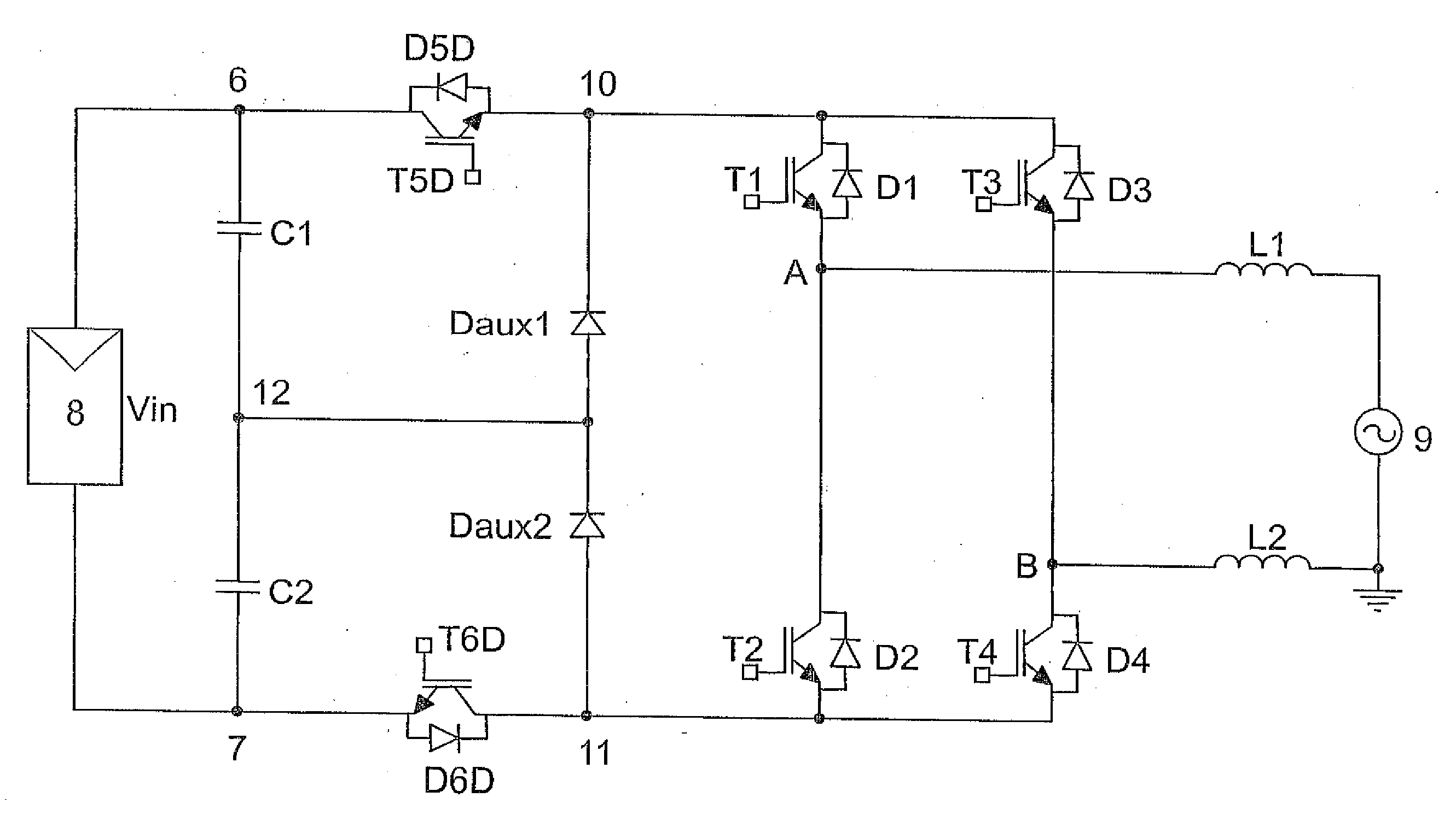
[0012]The invention described herein corresponds to a dc / ac inverter circuit specially applicable as a conversion stage in photovoltaic installations connected to the grid, as shown in FIG. 3.

[0013]Said circuit minimizes EMC problems, and has a higher efficiency than those previously proposed.

[0014]The circuit of the invention is a single-phase inverter that is connected to a direct current energy source and transforms it into alternating current energy to be fed into an electric grid. The topology of the inverter circuit essentially comprises:[0015]a temporary energy accumulator that can consist of one or more accumulators connected in series in one or more branches in parallel with the energy source, across the direct current connections of the circuit;[0016]an inverter that is configured as a full bridge or H-bridge comprising at least two parallel branches each with a pair of switching elements in series, consisting of MOSFET, IGBT or another type of transistor that adapts to th...


PUM


Abstract

The invention presents a structure for the conversion of direct current electric power into alternating current electric power, characterised in that it is simple, highly efficient and minimises the problem of electromagnetic compatibility. The circuit includes, in its first preferred embodiment, six switching elements governed by a command unit, four switches forming an H-bridge (T1, T2, T3, T4) and two auxiliary switches (T5D, T6D), and two auxiliary diodes (Daux1 and Daux2). The elements of the H-bridge switch at grid frequency, whereas T5D and T6D switch at high frequency by means of pulse width modulation (PWM), or other appropriate modulation techniques. The voltage of these auxiliary switching elements (T5D, T6D) is limited topologically to half the direct current input voltage (Vin), thereby reducing switching losses and resulting in a high performance converter.

Description

OBJECT OF THE INVENTION[0001]The present invention has its main field of application in the industry dedicated to the design of electronic devices and, more particularly, to those conceived within the sector of photovoltaic solar energy power systems.[0002]The object of the invention is to provide a dc / ac conversion structure specially designed for photovoltaic systems connected to the electric grid without a transformer, characterized in being simple, highly efficient and minimizing the problems of electromagnetic compatibility.BACKGROUND OF THE INVENTION[0003]Photovoltaic systems connected to the grid are today enjoying wide acceptance in our society, and are now being used with increasing frequency. Commonly, they involve installations formed by a group of solar panels and an electronic converter, called an inverter which conditions the energy produced by the panels and injects it into the electric grid.[0004]In most cases, the converters for these installations are private low-p...

Claims


Application Information

Patent Timeline
Patent Type & Authority Applications(United States)
IPC IPC(8): H02M7/5387
CPCY02E10/563H02J3/383H02J2300/24H02J3/381Y02E10/56H02J3/40
Inventor GONZALEZ SENOSIAIN, ROBERTOCALAHORRA, JAVIER COLOMAPALOMO, LUIS MARROYOTABERNA, JESUS LOPEZGURPIDE, PABLO SANCHIS
Owner INGETEAM POWER TECH
Why Eureka
Try Eureka