Device for Removing by Suction Drill Dust when Drilling Holes into Walls

a technology of suction drill and dust removal device, which is applied in the direction of maintenance and safety accessories, boring/drilling apparatus, thread cutting machine, etc., can solve the problems of only satisfying the effect of drill dust removal, affecting the quality of the finished product, and affecting the quality of finished products, etc., and achieves the effect of convenient handling and cheap production

Inactive Publication Date: 2009-12-24
ELECTROSTAR SCHOETTLE
View PDF8 Cites 18 Cited by
  • Summary
  • Abstract
  • Description
  • Claims
  • Application Information

AI Technical Summary

Benefits of technology

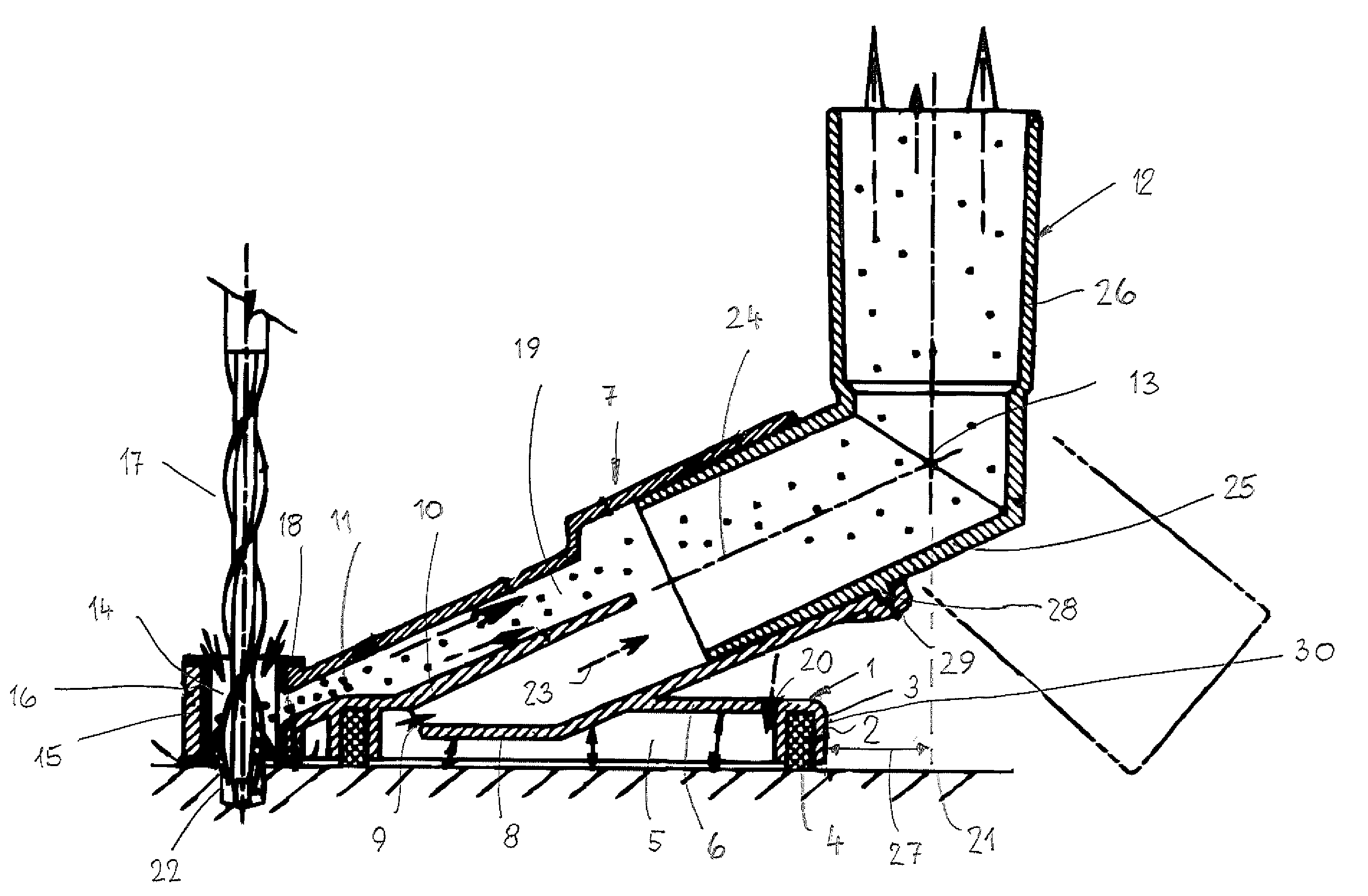
[0016]It is advantageous in this connection when the angle member is rotatable in the connecting socket. In this way, the part of the angle member that projects from the connecting socket can be adjusted into a favorable position for working.
[0017]In order for the load acting on the device by the connected vacuum hose to be as minimal as possible, the spacing of the intersection of the axes of the angularly positioned parts of the coupling member from the rear neighboring end of the device, viewed in a plan view onto the device, is minimal and is preferably zero. The projecting part generates a lever arm that as a result of this configuration is small so that onto the device in operation only a minimal force is acting. In this way it is prevented that the force acting on the device is greater than the vacuum-caused pressure forcing the device against the wall.
[0018]When the chamber wall that delimits the vacuum chamber, the suction sleeve, and the connecting socket are produced together as a monolithic part, the connecting device can be produced inexpensively and can be handled easily.

Problems solved by technology

This causes the wall area surrounding the drilling location to take on the color of the wall material that is being drilled so that after drilling and removing of the device there remains a stain on the wall about the drilling location.
The removal of the drill dust is however only effective to a satisfactory extent when the collecting chamber is located within the dropping area of the drill dust produced when drilling.
However, often it is necessary to drill a hole into the ceiling or an area close to the floor.
In this case, the drill dust reaches the collecting chamber only to an unsatisfactory extent.

Method used


Image

  • Device for Removing by Suction Drill Dust when Drilling Holes into Walls
  • Device for Removing by Suction Drill Dust when Drilling Holes into Walls

Examples


Embodiment Construction

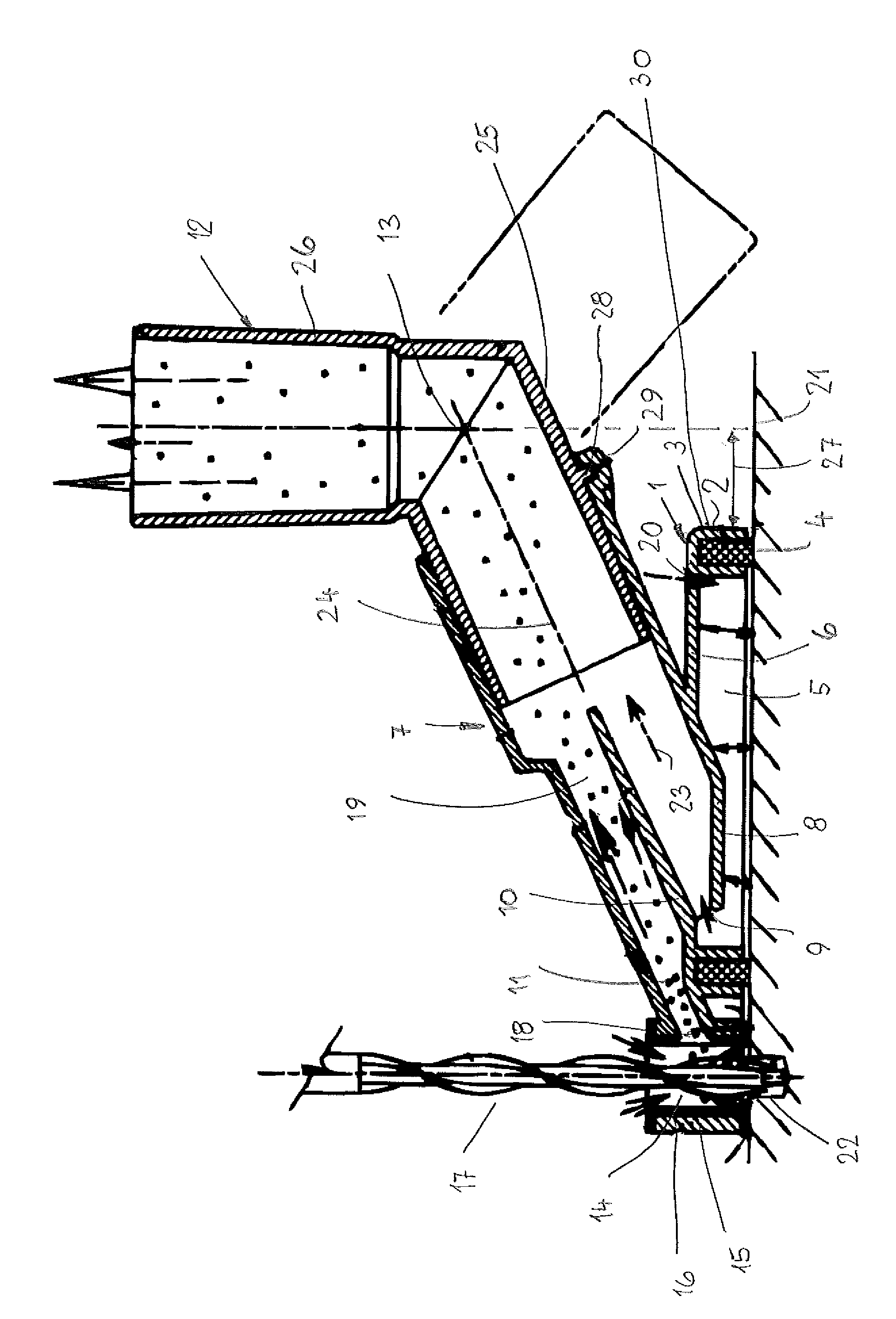
[0020]The removal device is used in order to remove by suction the drill dust produced when drilling a hole directly at the drilling location. The device has a base member 1 that can have any contour. About a portion of its circumference, the device has a rim 2 that is rectangularly angled and in which a recess 3 for receiving a seal 4 is provided. The seal 4 projects past the rim 2 and surrounds the vacuum chamber 5 which is delimited circumferentially by the rim 2 with seal 4 and by a cover part 6 of the base member 1. A tubular connecting socket 7 projects into the vacuum chamber 5 and is advantageously embodied monolithically together with the base member 1. The connecting socket 7 projects with most of its length past the base member 1. It projects with its end area 8 slightly into the vacuum chamber 5. The end area 8 has an opening 9 by means of which the vacuum chamber 5 is connected to the interior of the connecting socket 7.

[0021]A partition 10 is provided in the connecting...


PUM

PropertyMeasurementUnit
diameteraaaaaaaaaa
diameteraaaaaaaaaa
suctionaaaaaaaaaa

Abstract

A device for removing drill dust when drilling a hole into a wall has a base member and at least one vacuum chamber provided in the base member. At least one suction site is provided. A connector is connected to the base member and adapted to connect a vacuum unit that removes by suction at the suction site the drill dust produced by drilling. The at least one suction site and the at least one vacuum chamber are spatially separated from one another.

Description

BACKGROUND OF THE INVENTION[0001]The invention relates to a device for removing by suction drill dust when drilling holes into walls and the like, wherein the device comprises at least one vacuum chamber, at least one suction site and a connector for a vacuum unit that removes by suction at the suction site the drill dust produced by drilling.[0002]Such removal devices serve the purpose of removing by suction (i.e., by vacuuming) drill dust that is produced when drilling a hole into a wall at the drilling location so that the drill dust does not fall onto the ground. For this purpose, the device is connected to a vacuum hose of a vacuum cleaner so that the drill dust is removed from the drilling location. In this connection, a vacuum or underpressure is produced in the vacuum chamber and the vacuum ensures that the device is pulled tightly against the wall. The device therefore must not be held by hand during the drilling operation. The drill is inserted through an opening in the ch...

Claims


Application Information

Patent Timeline
Patent Type & Authority Applications(United States)
IPC IPC(8): B23B47/34
CPCB23B47/00B23B2270/30Y10T408/554Y10T408/50B23Q11/0046
Inventor BRUNTNER, EUGEN
Owner ELECTROSTAR SCHOETTLE
Why Eureka
Try Eureka