Strong high performance twist drill

a twist drill and high-performance technology, applied in the direction of twist drills, manufacturing tools, wood boring tools, etc., can solve the problems of high processing cost, low processing precision, and difficult processing conditions, and achieve the effect of increasing the angle of the groove and the thickness of the drill core, and increasing the drill strength against twisting

Inactive Publication Date: 2009-12-24
JIANGSU TIANGONG TOOLS CO LTD
View PDF19 Cites 13 Cited by
  • Summary
  • Abstract
  • Description
  • Claims
  • Application Information

AI Technical Summary

Benefits of technology

[0018]Above improvement is to grind back groove edge to increase groove shaped an

Problems solved by technology

Therefore, processing conditions are more complicated and difficult than those of turning and other cutting methods.
In addition, processing precision is relatively low and surface processed is relatively rough.
Traditional normal twist drill has the following main problems:1. Value of rake angle on each point of main cutting edge varies greatly and becomes negative where approaching drill core; hence cutting conditions are poor.2. Chisel edge is too long and cutting edge

Method used


Image

  • Strong high performance twist drill
  • Strong high performance twist drill
  • Strong high performance twist drill

Examples


embodiment 1

Preferred Embodiment 1

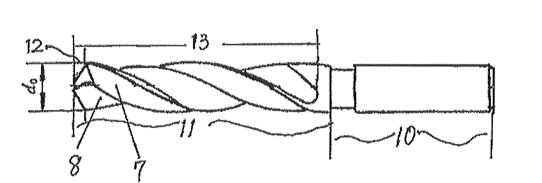
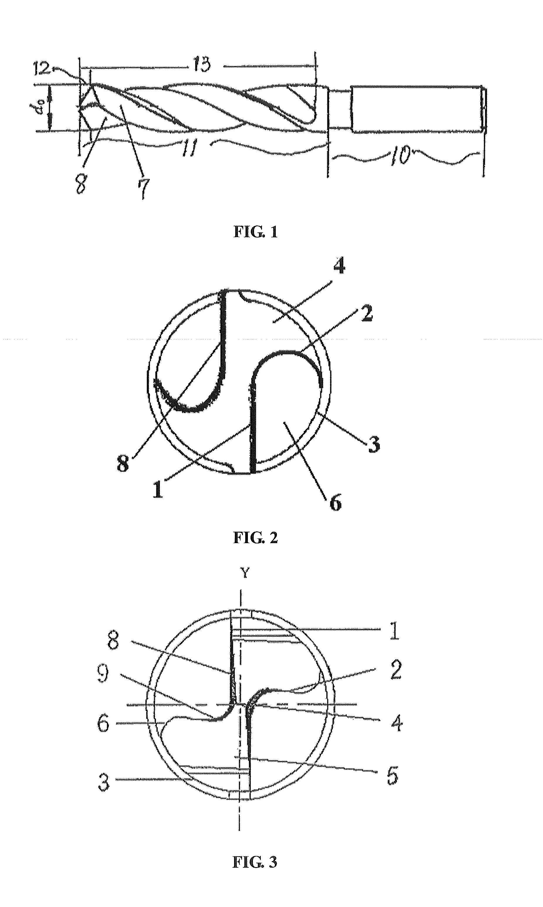
[0045]As shown in FIG. 3 and FIG. 4, a strong high performance twist drill of diameter of 0.25 mm, comprising shank 10 and working part 11. Said working part comprising cutting part 12 and guiding part 13. Said cutting part 12 consists of rake face 8, relief face 5, main cutting edge 1 and chisel edge 4. Said guiding part 13 consists of rear groove edge 2 and chip dividing groove 7. Main cutting edge tilts towards drill core from outside to inside. In cross section, included angle between main cutting edge 1 and center vertical line Y is 3°. Main cutting edge 1 and rear groove edge 2 intersects at narrow chisel edge 4. Length of narrow chisel edge is 0.03 mm. Rake angle at drill core is positive.

[0046]As shown in FIG. 3, transition edge at intersection between rear groove edge 2 and small outer arc face 3 is round angle.

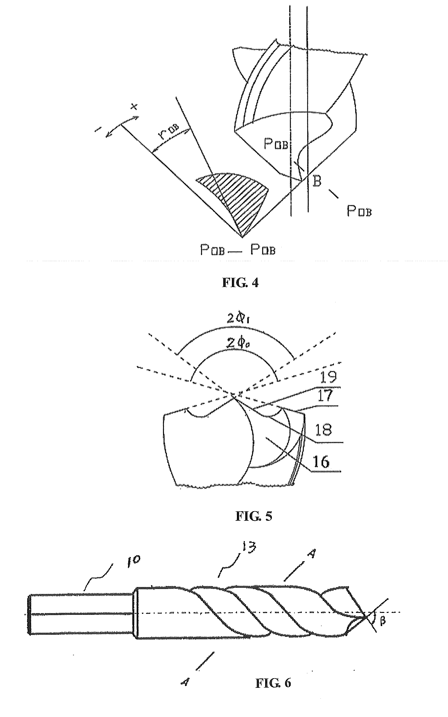
[0047]As shown in FIG. 6 and FIG. 7, groove shaped angle formed by main cutting edge 1 and back groove face 9 is an open V on cross section per...

embodiment 2

Preferred Embodiment 2

[0049]As shown in FIG. 3 and FIG. 4, a strong high performance twist drill of diameter of 30 mm, comprising shank 10 and working part 11. Said working part comprising cutting part 12 and guiding part 13. Said cutting part 12 consists of rake face 8, relief face 5, main cutting edge 1, and chisel edge 4. Said guiding part 13 consists of rear groove edge 2 and chip dividing groove 7. Main cutting edge tilts towards drill core from outside to inside. In cross section, included angle between main cutting edge 1 and center vertical line Y is 15°. Main cutting edge 1 and rear groove edge 2 intersects at narrow chisel edge 4. Length of narrow chisel edge is 0.25 mm. Rake angle at drill core is positive.

[0050]As shown in FIG. 3, transition edge at intersection between rear groove edge 2 and small outer arc face 3 is round angle.

[0051]As shown in FIG. 6 and FIG. 7, groove shaped angle formed by main cutting edge 1 and back groove face 9 is an open V on cross section per...

embodiment 3

Preferred Embodiment 3

[0053]As shown in FIG. 3 and FIG. 4, a strong high performance twist drill of diameter of 80 mm, comprising shank 10 and working part 11. Said working part comprising cutting part 12 and guiding part 13. Said cutting part 12 consists of rake face 8, relief face 5, main cutting edge 1, and chisel edge 4. Said guiding part 13 consists of rear groove edge 2 and chip dividing groove 7. Main cutting edge tilts towards drill core from outside to inside. In cross section, included angle between main cutting edge 1 and center vertical line Y is 25°. Main cutting edge 1 and rear groove edge 2 intersects at narrow chisel edge 4. Length of narrow chisel edge is 0.5 mm. Rake angle at drill core is positive.

[0054]As shown in FIG. 3, transition edge at intersection between rear groove edge 2 and small outer arc face 3 is round angle.

[0055]As shown in FIG. 6 and FIG. 7, groove shaped angle formed by main cutting edge 1 and back groove face 9 is an open V on cross section perp...


PUM

PropertyMeasurementUnit
Lengthaaaaaaaaaa
Angleaaaaaaaaaa
Angleaaaaaaaaaa

Abstract

A strong high performance twist drill which aims at providing a high performance twist drill to solve the existing problems effectively. The twist drill can reduce the change in value of the rake angle, increase the value of the rake angle especially at the position approaching the drill core, and improve the cutting condition. The twist drill comprises a shank and a working part. Said working part comprises a cutting part and a guiding part. Said cutting part includes a rake face, a relief face, a main cutting edge and a chisel edge; said guiding part includes rear groove edges and flutes; wherein, said main cutting edge tilts towards the drill core from outside to inside; the angle between the main cutting edge and the center vertical line at the cross section is in the range of 3-25°; said main cutting edge intersects with back groove face at the narrow chisel edge; the length of the narrow chisel edge is in the range of 0.03-0.5 mm; and the rake angle at the drill core is positive.

Description

TECHNICAL FIELD[0001]This utility model relates to a type of hole processing tool, in particular a type of twist drill.BACKGROUND OF INVENTION[0002]As shown in FIG. 1, the twist drill is the most widely used hole processing tool. Normally, diameter range is 0.25˜80 mm. A twist drill mainly consists of a working part and a shank. The working part includes two spiral grooves. Helix angle of twist drill mainly affects rake angle on cutting edge, strength of edge clack, and chip removal performance, and is normally 25°˜32°. Spiral grooves can be processed by milling, grinding, hot rolling, or hot extrusion etc. After tool grinding, front end of drill becomes cutting part. Vertex angle of cutting part of standard twist drill is 118°. Chisel edge angle is 40°˜60°. Angle of relief is 8°˜20°. Due to structural causes, rake angle is large at outer part and gradually decrease toward middle part. At chisel edge, rake angle is negative (can reach about −55°). During drilling, chisel edge functi...

Claims


Application Information

Patent Timeline
IPC IPC(8): B23B51/02
CPCB23B51/02B23B2251/04Y10T408/9097B23B2251/18B23B2251/14
Inventor ZHU, XIAOKUN
Owner JIANGSU TIANGONG TOOLS CO LTD
Why Eureka
Try Eureka