Method and device for cooling a component of a turbine

a technology of turbine components and cooling devices, which is applied in the direction of machines/engines, stators, liquid fuel engines, etc., can solve the problems of additional performance losses, increased costs, and inability to achieve minimum clearance, so as to improve the overall performance of the gas turbine, reduce the effect of tip clearance and temperature ris

Inactive Publication Date: 2009-12-24
SIEMENS AG
View PDF19 Cites 12 Cited by
  • Summary
  • Abstract
  • Description
  • Claims
  • Application Information

AI Technical Summary

Benefits of technology

[0039]One further advantage of the invention is that there is no risk of back flow at off design conditions, e.g. low loads, which requires conventional clearance control systems to change the air supply to a further downstream location in the compressor still having a positive drive pressure. A change of flow direction can otherwise, if the same air supply is connected to the bearings of the gas turbine, suck lubricant oil out of the bearings generating risks for fire and build up of carbon deposits in seals. If needed for circumventing pinch points (contact clearance) during hot restarts a valve may be used to shut off the air flow through the cooling circuit. When using an ejector as a pressure booster for the cooling air no extra moving parts including valves are required. If the cooling circuit is shut off the small flow of bleed air from the compressor will simply be discharged through the air intake for the mainstream flow in the ejector.
[0040]The overall performance for the gas turbine is improved due to the minimized tip clearance and no additional loss of mass flow and compressor work when not utilising the bled off air fully. The cooling air injected / sucked into the compressor has a higher temperature after cooling the component, for example the turbine casing, compared to the main flow in the compressor at the location where the air is discharged. Since the cooling air flow is anticipated to be only a small fraction of a percent of the total flow this negative impact on performance is more than compensated by advantages elsewhere.

Problems solved by technology

This may have at least two effects, one being that due to the higher temperature of the cooling air a minimum clearance can not be achieved at all or only by using excessive mass flows, the other being that after the cooling task the air is released in the flue gases still having a surplus pressure without producing any work which generates additional performance losses.
The pre-cooling requires more components and / or more systems, adds costs and potentially decreases the reliability and availability.
This solution does not require any extra cooling air, is able to deal with transient movements but is slow and requires expensive materials in large components, which means that it adds costs.

Method used


Image

  • Method and device for cooling a component of a turbine
  • Method and device for cooling a component of a turbine
  • Method and device for cooling a component of a turbine

Examples


Embodiment Construction

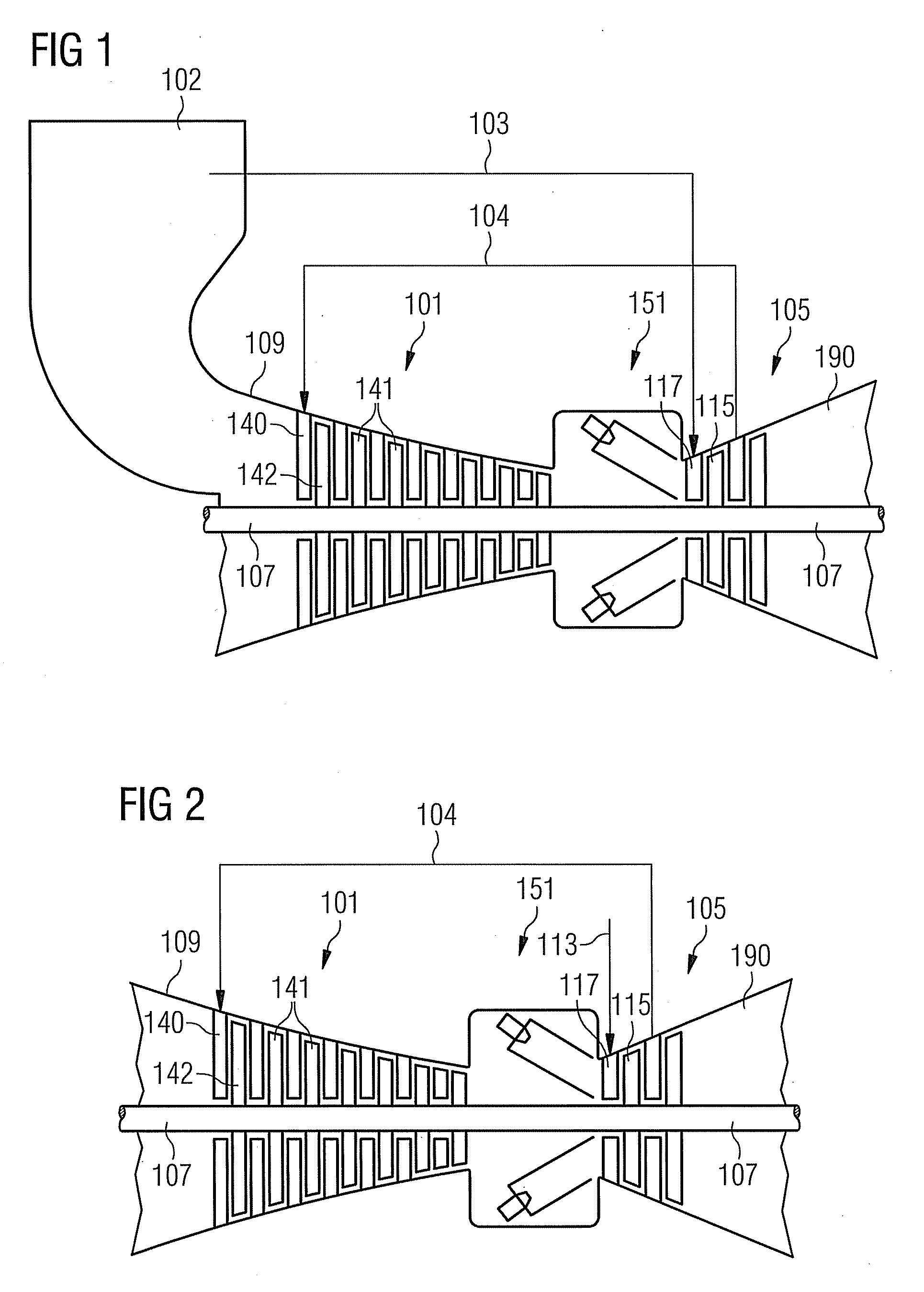
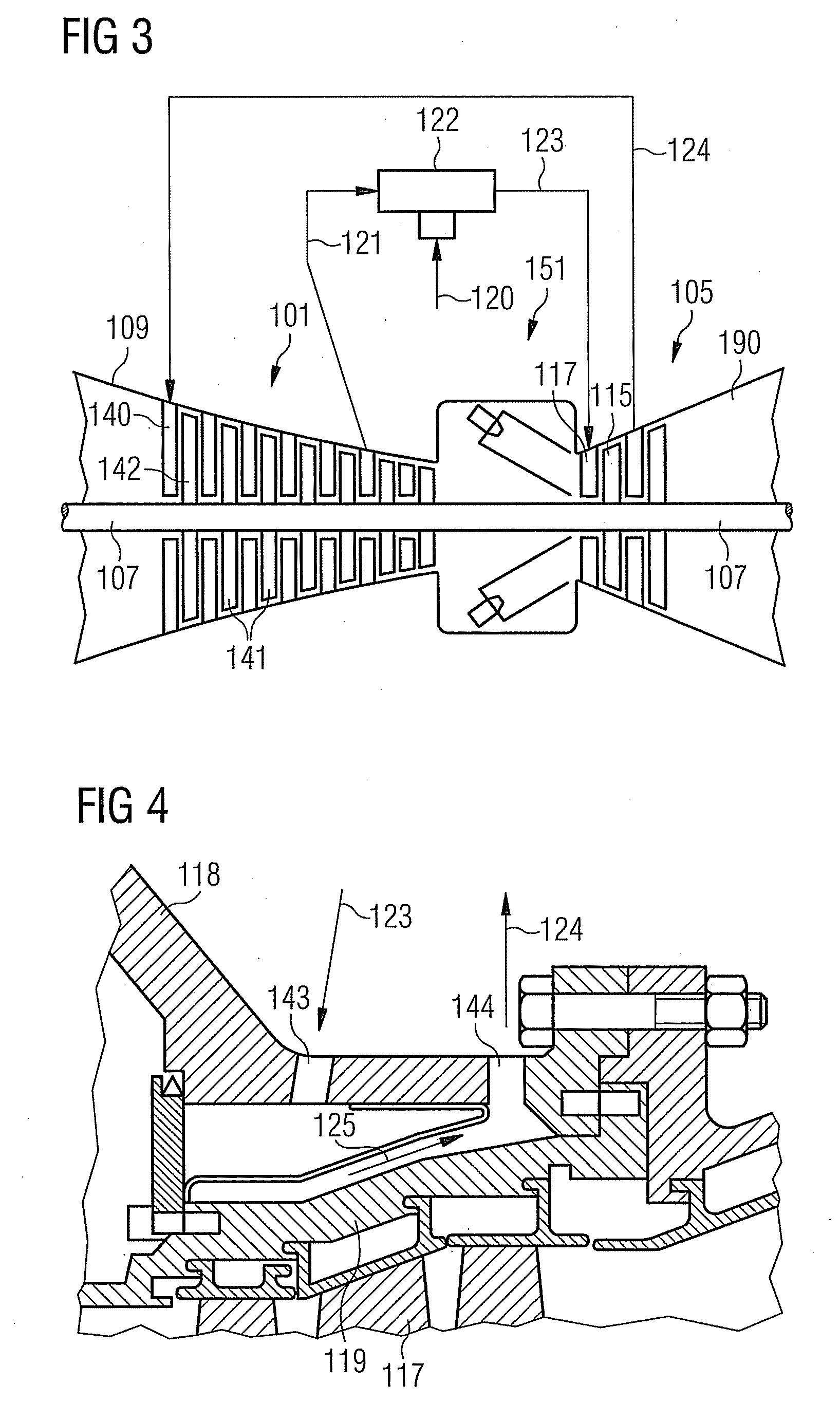
[0047]An embodiment of the present invention will now be described with reference to FIGS. 1 to 5. FIG. 1 schematically shows an inventive gas turbine. The gas turbine comprises a rotation axis with a rotor. The rotor comprises a shaft 107. Along the rotor a suction portion with a casing 109, a compressor 101, a combustion portion 151, a turbine 105 and an exhaust portion with a casing 190 are located.

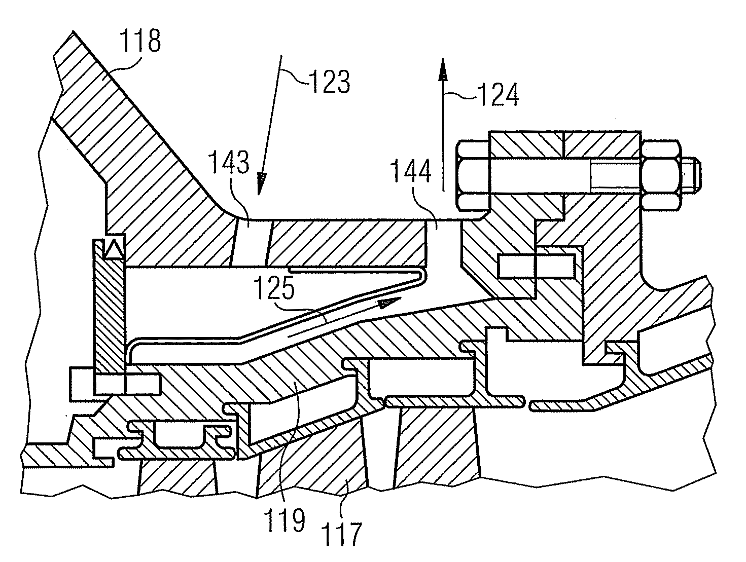
[0048]The combustion portion 151 communicates with a hot gas flow channel which may have a circular cross section, for example. The turbine 105 comprises a number of turbine stages. Each turbine stage comprises rings of turbine blades. In flow direction of the hot gas in the hot gas flow channel a ring of turbine guide vanes 117 is followed by a ring of turbine rotor blades 115. The turbine guide vanes 117 are connected to an inner casing of a stator. The turbine rotor blades 115 are connected to the rotor. The rotor is connected to a generator, for example.

[0049]During operation of th...


PUM


Abstract

A method for cooling a component of a turbine is provided, wherein a fluid with a pressure below 1 bar is guided away from the component. Moreover, a turbine is described comprising a component, a conduit which is connected to the component so that a fluid can be guided away from the component, and a fluid discharge which is connected to the conduit. The fluid discharge is constructed so that it removes a fluid with a pressure below 1 bar.

Description

CROSS REFERENCE TO RELATED APPLICATIONS[0001]This application claims priority of European Patent Office application No. 08011428.3 EP filed Jun. 24, 2008, which is incorporated by reference herein in its entirety.FIELD OF INVENTION[0002]The present invention relates to a method for cooling a component and to a turbine.BACKGROUND OF INVENTION[0003]In order to achieve high component efficiencies for a turbine and ultimately a gas turbine cycle itself small tip clearances are required. This is even more important for small gas turbines where the relative clearance is increased due to manufacturing limitations and tolerances. One way of controlling the tip clearance in the turbine is to actively cool the casing. For example, the thermal expansion of the casing is matched with the rotor to minimize the clearance without taking the risk of interference during transient and hot restarts.[0004]This type of cooling requires cooling air being bled from the compressor. In small gas turbines ha...

Claims


Application Information

Patent Timeline
Patent Type & Authority Applications(United States)
IPC IPC(8): F01D5/08
CPCF01D11/24F05D2260/601F02C7/18F01D25/12
Inventor DOWN, ANDREWNILSSON, ULF
Owner SIEMENS AG
Why Eureka
Try Eureka