
Fire suppression delivery system

Inactive Publication Date: 2009-12-31
THOMAS MICHAEL STEVEN
View PDF47 Cites 43 Cited by
  • Summary
  • Abstract
  • Description
  • Claims
  • Application Information

AI Technical Summary

Benefits of technology

[0030]Another object of this invention is to develop the Fire Suppression Delivery System Hybrid Smart Fire Extinguishment Encasement is to extend the capacity of the smart encasement to hover and discharge or

Problems solved by technology

Whereas a primary fire or primary area fire may be accessible to firefighters, fires existing at the same time within these secondary areas or substructures often are not (as readily accessible): thereby requiring firefighters to venture further into a burning structure to attack a substructure fire or rely more upon the surround and drown and other techniques.
This concern may be exacerbated where fire extinguishment systems within the sub area have failed or are nonexistent: the fire within will continue, creating a greater conflagration, and pose a risk to property and firefighters fighting the blaze within the primary structure.
As discussed at Fire Suppression Delivery System, Ser. No. 11 / 349,785, a problem exists with using a VTOL wing configuration for fire zone combat, even in the Hybrid Smart Fire Extinguishment Encasement.
Unless shrouded from airborne projectiles common to a fire environment or the projection of surface areas that could impact the turbine, the ducted rotor design (U.S. Pat. No. 6,976,653) is limited as a propulsion method for the Hybrid Smart Fire Extinguishment Encasement.
The use of or sole use of an air-breathing propulsion means raises a concern when applied to a fire environment, where smoke, particulate matter, reduced oxygen levels, etc, can compromise operations.
The use of high impact filters may overcome part of the latter concern, while also increasing weight, costs and reducing fire extinguishment material containment space: though not addressing the matter of reduced oxygen levels.
However, the approach taken by many of the improved systems is met with several limitations (aside from size and cost) when applied to Hybrid Smart Fire Extinguishment Encasement requirements.
Therefore, structural fires, underground structures and underwater structure fires requiring the use of a GPS linked collision and avoidance, would be compromised and rendered ineffective.
However, where U.S. Pat. No. 6,727,841 uses “transmitting an electromagnetic signal from a high altitude unmanned air vehicle to an urban environment including between buildings; receiving by a low altitude unmanned air vehicle a plurality of electromagnetic rays from said electromagnetic signal from said transmitting step, said electromagnetic signal diffracting and reflecting off buildings in said urban environment, an electric field at said low altitude unmanned air vehicle defined as ##EQU1##,” the use of ##EQU1## by the Hybrid Smart Fire Extinguishment Encasement may not be practical: the Hybrid Smart Fire Extinguishment Encasement is required not only to interrogate a structural area but to maneuver within and through same, target and acquire a fire zone for extinguishment purposes.
The effectiveness of transmitting an electromagnetic signal from a high altitude unmanned air vehicle, again may not be practical for use here.
Additional concerns arise here that may limit adaptation of this system for deployment with the Hybrid Smart Fire Extinguishment Encasement: effective transmission of electromagnetic signals through the structure and costs.
The use of GPS to assist in collision avoidance of a Hybrid Smart Fire Extinguishment Encasement may not be viable at this time, for several reasons: de minimus, the inability of a signal to effectively penetrate a concrete and metal structure, constant change within a fire environment and whether such has the ability to detect debris and projectiles within the fire environment before it can damage an encasement.
However, it does not address the need of the Hybrid Smart Fire Extinguishment Encasement's thermal tolerance threshold to be higher than that of other fire extinguishment encasements, given the need to endure (prolonged) exposure to extreme heat conditions within a fire environment.

Method used


Image

  • Fire suppression delivery system
  • Fire suppression delivery system
  • Fire suppression delivery system

Examples


Embodiment Construction

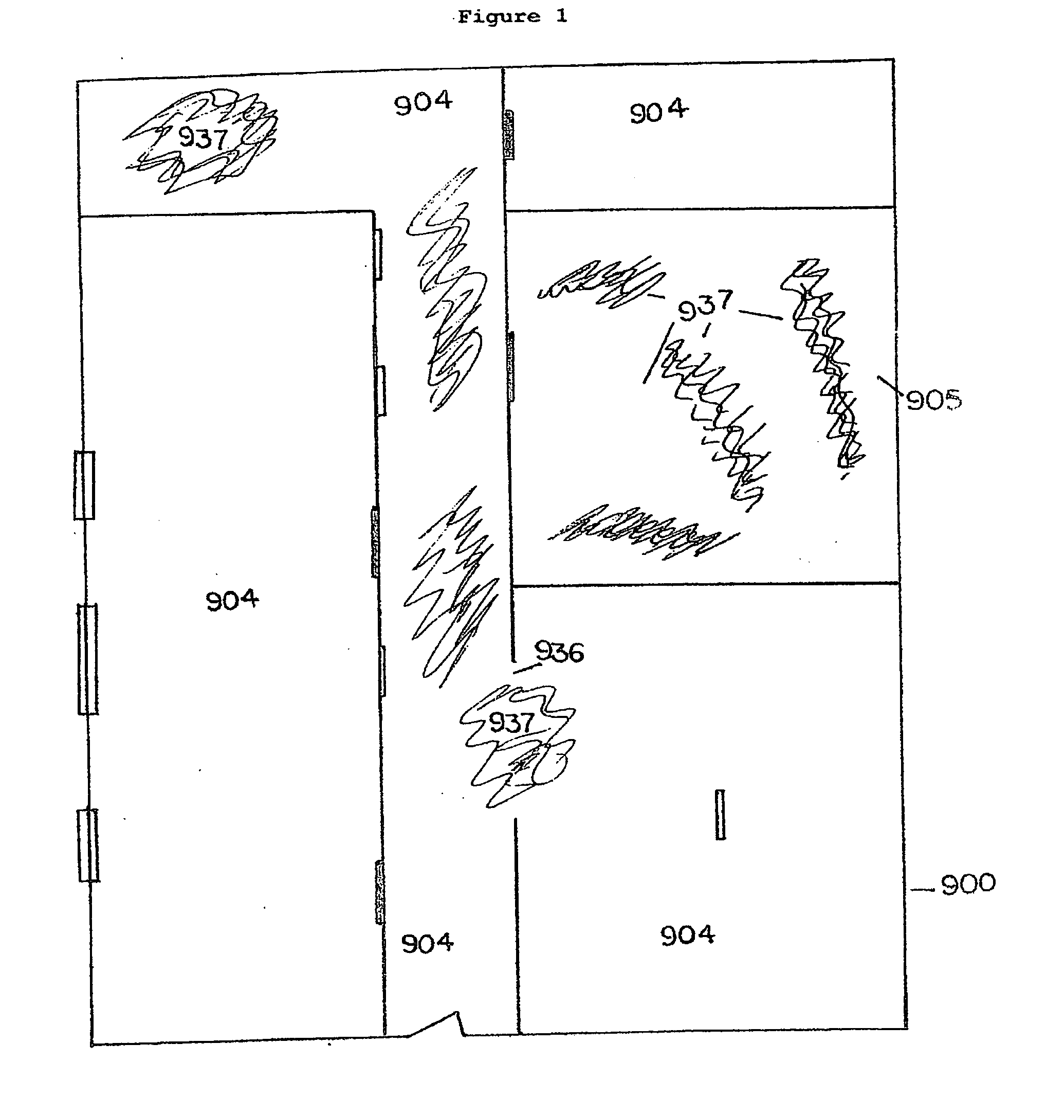
[0041]As used herein, a fire situation, fire environment, fire situation, fire zone or fire conflagration, (used interchangeably, unless specified otherwise) shall mean the place, environment, area or ecosystem where a fire exists, is active, is anticipated, or has existed but requires continued monitoring. Such terms may also be used interchangeably with fire, target, target area, or target zone.

[0042]As used herein, a fire extinguishment material, a fire suppressant material, a fire retardant material, an endothermic agent, shall be defined as a powder, granular, solid, aerosol, misting material, atomizing mist, foam firefighting material, inert gas, gaseous substance, or similar material, in a compressed or non-compressed state, or other suitable substance, with suitable characteristics for fire extinguishment, fire suppression, fire retardant, particulate matter suppression and / or dispersal, the capacity to reduce the temperature within a fire zone when delivered to and activate...


PUM


Abstract

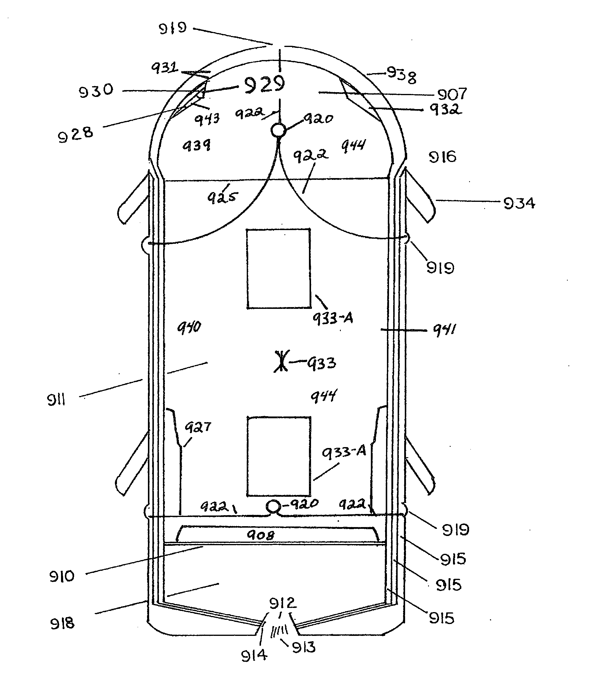
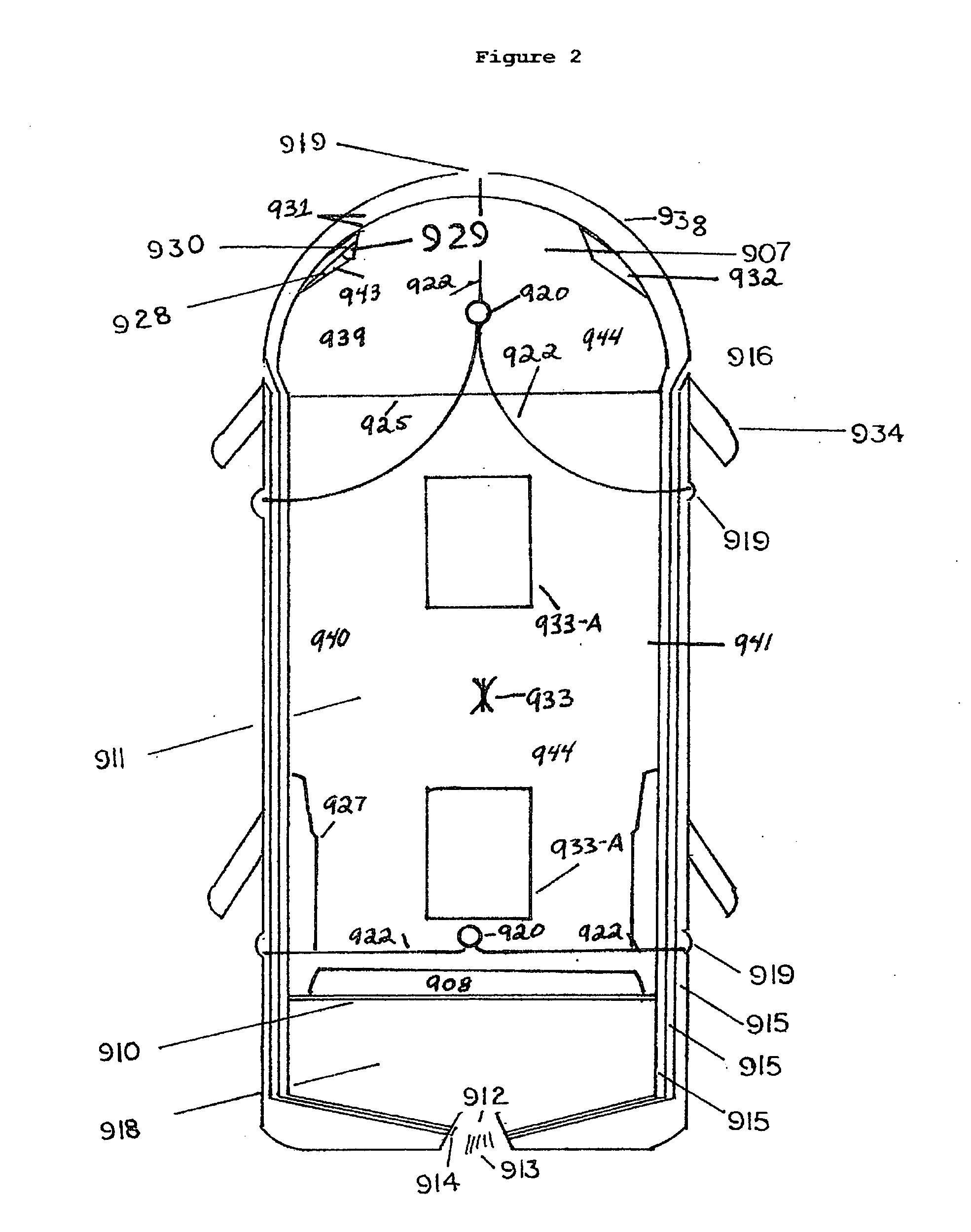
Within the Fire Suppression Delivery System the fire extinguishment encasement is modified to produce a hybrid smart fire extinguishment encasement incorporating drone-like functions to effect fire suppression. This will allow for standard smart fire extinguishment encasement deployment or an extended range, propulsion assisted smart fire extinguishment encasement with the capacity to navigate within a structure and hover within same, in anticipation of access to an obstructed fire zone, discharge while hovering, surface attached or on-the-fly.

Description

[0001]This application is a continuation-in-part application of U.S. Ser. No. 11 / 349,785, filed Feb. 7, 2006, which is a continuation-in-part application of U.S. Ser. No. 10 / 902,598 (herein, referred to as Publication No. 20050139363) filed Jul. 29, 2004, which claims benefit of Provisional Patent Application No. 60 / 491,816. The content of which is incorporated in its entirety into this application by reference.[0002]All literature cited herein are incorporated in their entirety by reference into this application.BACKGROUND OF THE INVENTION[0003]This is a Fire Suppression Delivery System for the delivery of current, Next Generation, and future developments in the area of materials to extinguish, suppress or retard fires in, but not limited to high rise, commercial and industrial buildings; tunnel structures; offshore structures and marine platforms; marine vessels; and environmental areas.[0004]The application of the Fire Suppression Delivery System is the ability to place fire exti...

Claims


Application Information

Patent Timeline
IPC IPC(8): A62C31/22
CPCA62C5/02A62C3/025
Inventor THOMAS, MICHAEL STEVEN
Owner THOMAS MICHAEL STEVEN
Learn More