Power unit support structure

a support structure and power unit technology, applied in the direction of dampers/springs, shock absorbers, dampers/spring combinations, etc., can solve the problems of idling vibration, high dynamic spring, difficulty in achieving sufficient vibration-damping action against such yawing vibration, etc., to achieve high attenuating action high attenuating action

Inactive Publication Date: 2009-12-31
SUMITOMO RIKO CO LTD
View PDF7 Cites 22 Cited by
  • Summary
  • Abstract
  • Description
  • Claims
  • Application Information

AI Technical Summary

Benefits of technology

[0029]According to this mode, vibrations that have been input across the first mounting member and the second mounting member in the first fluid-filled vibration-damping device can be consistently transmitted between the first input member and the second input member in the second fluid-filled vibration-damping device, while relative pressure fluctuations between the pressure-receiving chamber and the equilibrium chamber in the

Problems solved by technology

Typically it will take the form of large-amplitude vibration in a low frequency range of around 10 Hz, so in rear engine mounts of conventional design, it was difficult to attain sufficient vibration-damping action against such yawing vibration.
However, idling vibration, which has a somewhat higher frequency than crank vibration, is also known to be vibration that occurs in the roll direction.
Moreover, vibration-damping action produced by an orifice passage will be effective only in the relatively narrow frequency range to which the orifice passage has been tuned, and

Method used


Image

  • Power unit support structure
  • Power unit support structure
  • Power unit support structure

Examples


first embodiment

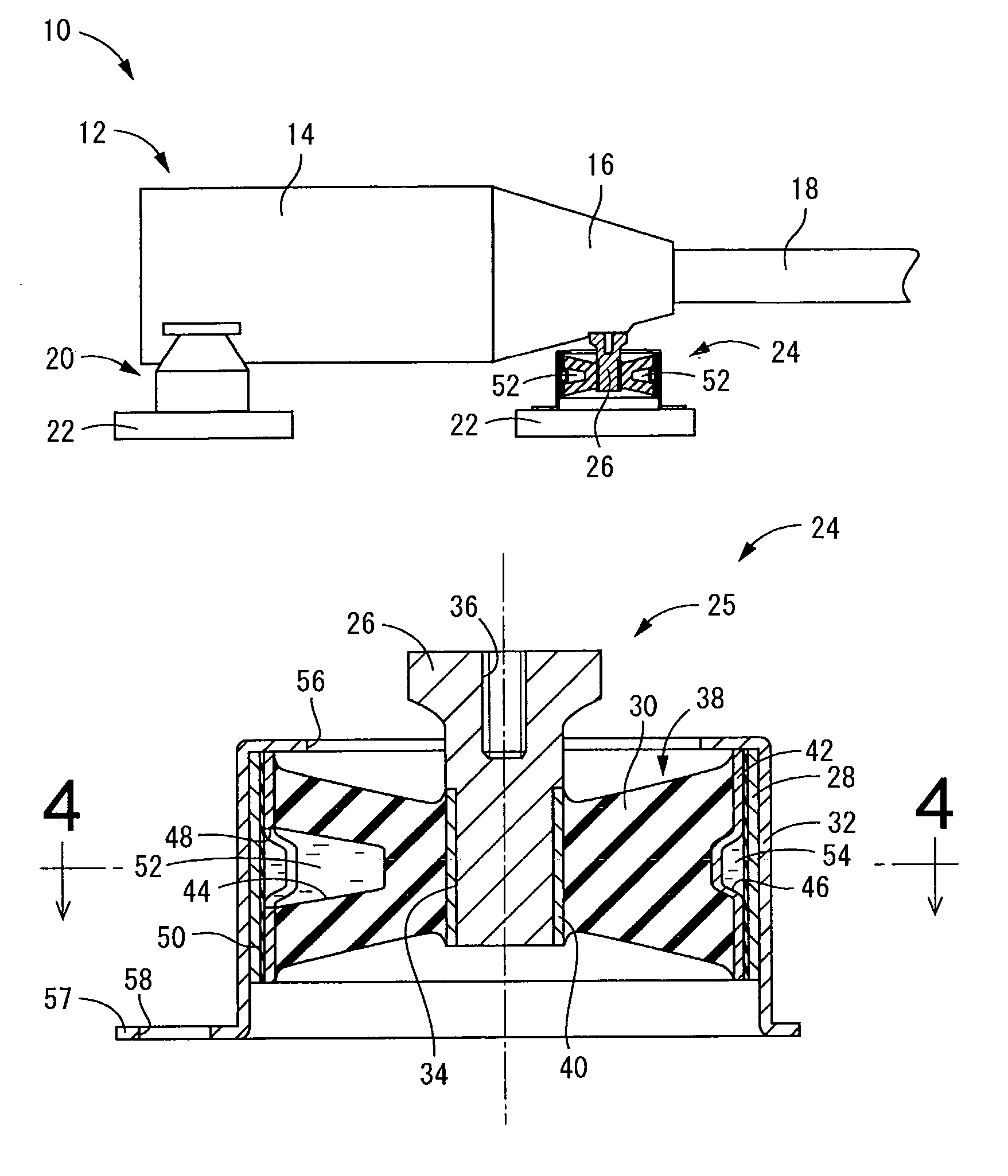
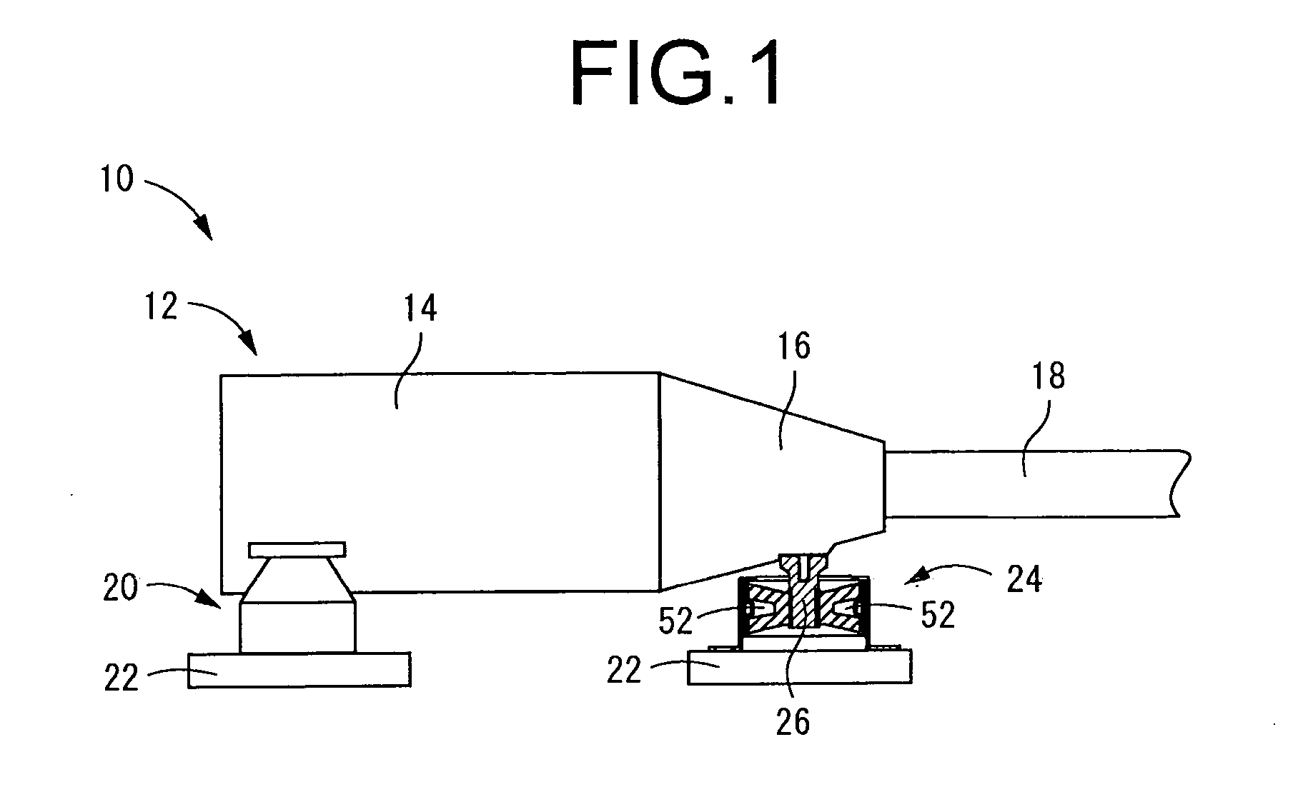
[0048]FIG. 1 depicts in simplified form a side view showing an entire power unit support structure 10 according to the present invention. The power unit 12 is a power unit for an automobile of FR design, and includes an engine unit 14 provided as the internal combustion engine, and a transmission unit 16 provided as the gear box. Output and torque generated by the engine unit 14 are adjusted by the gear train of the transmission unit 16 to the level of output and torque required for driving the vehicle, and are output to an output shaft (not shown), then transmitted as rotational driving force to from the output shaft via a propeller shaft 18 to the drive wheels, i.e. the rear wheels.

[0049]To describe in greater detail, the power unit 12 is oriented lengthwise in the vehicle longitudinal direction so that the direction of extension of the propeller shaft 18 is aligned with the vehicle longitudinal direction (the sideways direction in FIG. 1), with the engine unit 14 situated towards...

second embodiment

[0064]FIGS. 5 to 7 depict a rear engine mount 60 situated towards the vehicle rear end in a power unit support structure according to the present invention. The rear engine mount 60 includes a first fluid-filled vibration-damping device 66 that has a pair of integrally vulcanization-molded components 62 secured fitting externally onto the first mounting member 26, to either side of an orifice fitting 64.

[0065]The pair of integrally vulcanization-molded components 62, 62 are comparable in construction to one another, each having a middle sleeve 70 with a large-diameter tube profile disposed to the outside peripheral side of an inner sleeve 68 with a small-diameter tube profile, and positioned approximately concentrically with and spaced apart diametrically to the outside of the inner sleeve 68 so as to encircle it; and a sectional main rubber elastic body 72 interposed between the inner sleeve 68 and the middle sleeve 70 so that these are elastically linked by the sectional main rubb...


PUM


Abstract

A power unit support structure adapted to provide vibration-damped support of an power unit of an automobile of FR longitudinal engine design on a vehicle body via engine mounts situated at two locations towards a vehicle front end and one location towards a vehicle back end, respectively. Of the engine mounts disposed at the three locations, a fluid-filled vibration-damping device exhibiting vibration-attenuating action based on flow action of non-compressible fluid filling the interior thereof is employed as a rear engine mount disposed at the vehicle back end, and the vibration-attenuating action based on the flow action of the non-compressible fluid is exhibited against vibration input in a vehicle longitudinal direction.

Description

INCORPORATED BY REFERENCE[0001]The disclosure of Japanese Patent Application No. 2008-171089 filed on Jun. 30, 2008 including the specification, drawings and abstract is incorporated herein by reference in its entirety.BACKGROUND OF THE INVENTION[0002]1. Field of the Invention[0003]The present invention relates in general to a power unit support structure adapted to provide vibration-damped support of an automobile power unit on a vehicle body, and relates in particular to a power unit support structure adapted to provide effective vibration-damping action against yawing vibration of the power unit.[0004]2. Description of the Related Art[0005]As well known in the art, an automotive power unit integrally incorporating an engine and transmission is provided with vibration-damped support on the vehicle body at several locations by engine mounts in order to reduce transmission of vibration to the vehicle body. Particularly in the case of a longitudinal engine in an FR (front engine / rear...

Claims


Application Information

Patent Timeline
IPC IPC(8): F16F11/00
CPCF16F13/16F16F13/1463
Inventor HAMADA, MASAAKIIHARA, YOSHIOISHIKAWA, RYOTA
Owner SUMITOMO RIKO CO LTD
Why Eureka
Try Eureka