Process for manufacturing a panel made of a thermoplastic composite

Active Publication Date: 2009-12-31
AIRBUS OPERATIONS SAS
View PDF17 Cites 16 Cited by
  • Summary
  • Abstract
  • Description
  • Claims
  • Application Information

AI Technical Summary

Benefits of technology

[0023]The aforementioned fabrics then make it possible to perform satisfactory draining of the gases during the consolidation step of the stack, in connection with the set of polyimide films partially overlapping each other.
[0024]Still preferably, the method also comprises a step for placement of at least one wedge limiting the edge effects likely to occur during the later consolidation step of the stack, each wedge being arranged along one edge of this stack. Preferably, the entirety of the perimeter of the stack is equipped with such wedges, which therefore allow savings in material. The positive influence on the aforementioned edge effects results from the fact that these wedges make it possible to limit the flow of transverse material. Indeed, during the compacting operation, the compacting plate “presses on” the stack of plies. Under the effect of this pressure, the resin, which is very fluid at this temperature, tends to flow toward the edge of the plate. It “abuts” against the aforementioned wedges, also called caulking wedges. When the compacting plate reaches the caulking wedges, it ex

Problems solved by technology

In the embodiments known from the prior art, the compacting plate usually comes into contact with the stack of plies of fibers during the consolidation step, which can harm the final quality of the panel obtained.
Indeed, it is first indicated that with this method, the surface state of the compacting plate greatly risks being imprinted on the upper surface of the panel obtained at the end of the consolidation step, which may sometimes lead to incompatibility with the high

Method used


Image

  • Process for manufacturing a panel made of a thermoplastic composite
  • Process for manufacturing a panel made of a thermoplastic composite
  • Process for manufacturing a panel made of a thermoplastic composite

Examples


Embodiment Construction

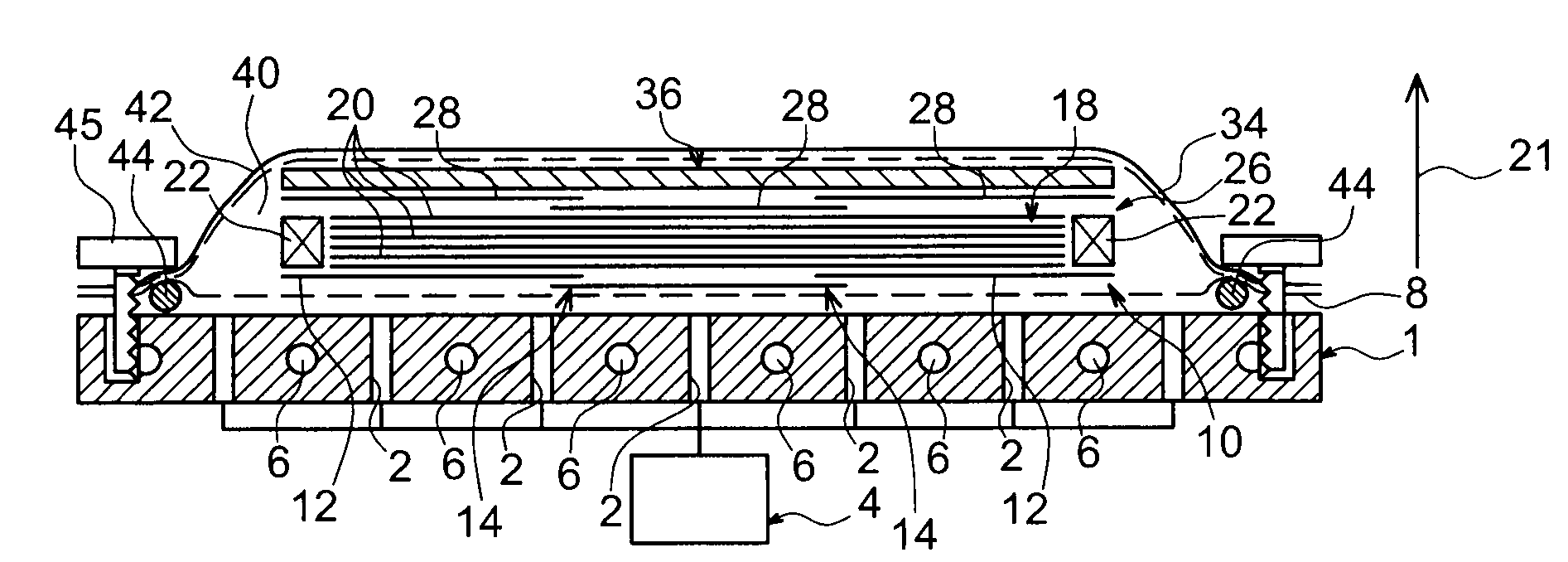
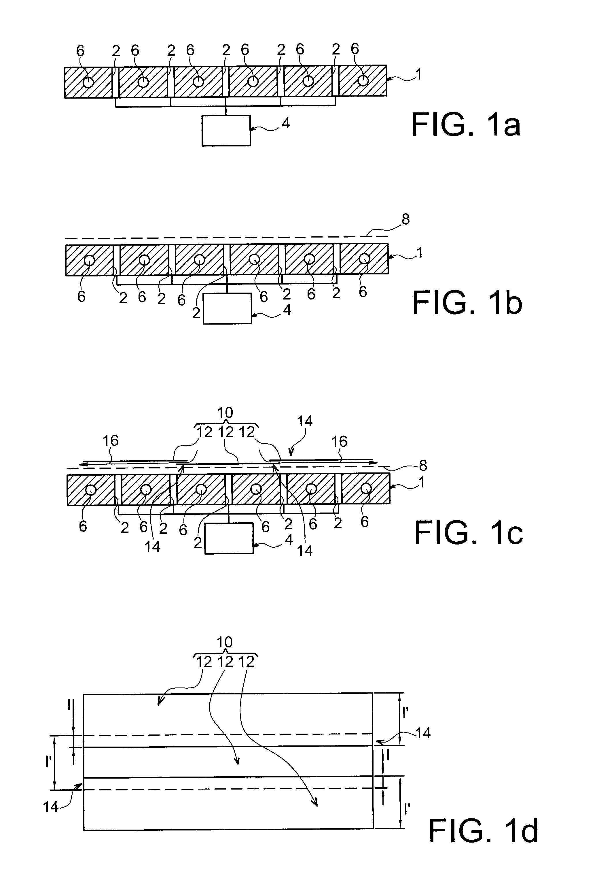
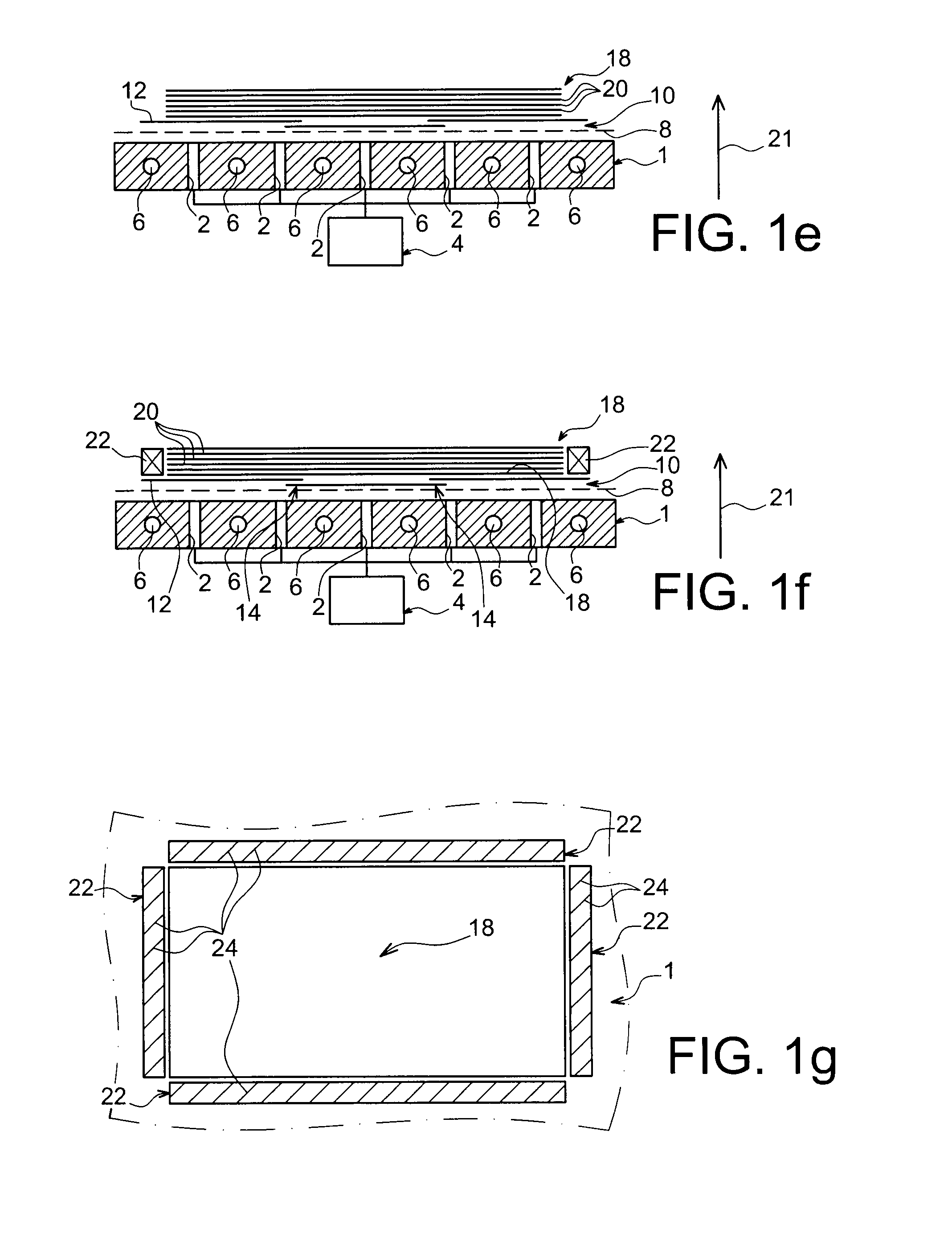
[0042]In reference first to FIGS. 1a to 1k, one can see different successive operations performed during the implementation of a method for manufacturing a panel in a composite material, according to a first preferred embodiment of the present invention. In this first embodiment, the panel which one wishes to obtain has a substantially flat shape, and for example globally square or rectangular, and has a thickness between 1 and 20 mm. For information, it is noted that this finds a particular application in the aeronautics as field as a fuselage panel for an aircraft, including a fiber ratio close to 65%, for example.

[0043]In FIG. 1a, one can see that the tooling used for the implementation of this method first comprises a support which can be likened to a marble plate referenced 1. This plate 1 is passed through perpendicularly, relative to the plane along which it extends, by a plurality of through orifices 2 provided within this marble plate 1. As will be detailed more explicitly ...


PUM

PropertyMeasurementUnit
Thicknessaaaaaaaaaa
Pressureaaaaaaaaaa
Thermoplasticityaaaaaaaaaa

Abstract

A method of manufacturing a panel made of a composite material using a tool having a support on which a lay-up is performed, the lay-up producing a stack of plies of fiber prepregs, followed by consolidating the stack aiming to obtain the panel using a compacting plate arranged above the stack. The method is implemented such that a first set of polyimide films partially covering each other is located in contact with the stack of plies, between the latter and the compacting plate.

Description

TECHNICAL FIELD[0001]The present invention relates generally to a method for manufacturing a panel made of a composite material, in particular a thermoplastic composite. For information, this may in fact involve composite materials with a PEEK resin or PPS resin thermoplastic matrix and long carbon fibers, but also possibly composites with an epoxy resin thermosetting matrix and carbon fibers.[0002]The invention preferably relates to a method for manufacturing panels having a thickness between approximately 1 and 20 mm, such as those typically found in the aeronautic field, which constitutes a particular application for the present invention. Indeed, the method which is the object of the invention can be implemented in order to obtain an aircraft fuselage panel, which usually has a fiber ratio close to 65%. To this end, implementation of the invention can indifferently lead to obtaining a substantially flat panel, or to obtaining a so-called single- or double-curvature panel traditi...

Claims


Application Information

Patent Timeline
IPC IPC(8): B29C70/44B29C70/30
CPCB29C33/68B29C37/0064B29C43/3642B29C70/44B29C70/543Y02T50/433B29K2079/08B29K2081/04B29K2307/00B29L2031/3082B29K2071/00Y02T50/40
Inventor KURTZ, DIDIERPAUCHET, STEPHANEBOUVET, DAVIDCHALLET, MARC
Owner AIRBUS OPERATIONS SAS
Why Eureka
Try Eureka