Apparatus for carrying out improved control of rotary machine

a technology of power converter and apparatus, which is applied in the direction of multiple motor speed/torque control, starter details, dynamo-electric motor/converter, etc., can solve the problems of sudden change of generated torque of three-phase motor, difficult maintenance, and low maintenance efficiency, so as to improve the control performance of the rotary machine, the effect of high level

Active Publication Date: 2009-12-31
DENSO CORP
View PDF8 Cites 76 Cited by
  • Summary
  • Abstract
  • Description
  • Claims
  • Application Information

AI Technical Summary

Benefits of technology

[0020]In view of the background, an object of at least one aspect of the present invention is to provide apparatuses for controlling at least one controlled variable of a rotary machine; these apparatuses are improved to maintain, at a high level, the performance of the control of the rotary machine even if the voltage utilization factor is shifted from its high region to its low region.

Problems solved by technology

However, at the moment when the control mode is shifted from the single-pulse control mode to the PWM control mode, a voltage required for the three-phase motor to create a torque generated immediately before the shift may not be obtained in the PWM control mode.
When the voltage required for the three-phase motor to create the torque generated immediately before the shift is not obtained in the PWM control mode, the shift may cause the generated torque by the three-phase motor to be suddenly changed.
This may make it difficult to maintain, at a high level, the performance of the current feedback control when the control of the inverter is shifted from the single-pulse control mode to the PWM control mode.

Method used


Image

  • Apparatus for carrying out improved control of rotary machine
  • Apparatus for carrying out improved control of rotary machine
  • Apparatus for carrying out improved control of rotary machine

Examples


first embodiment

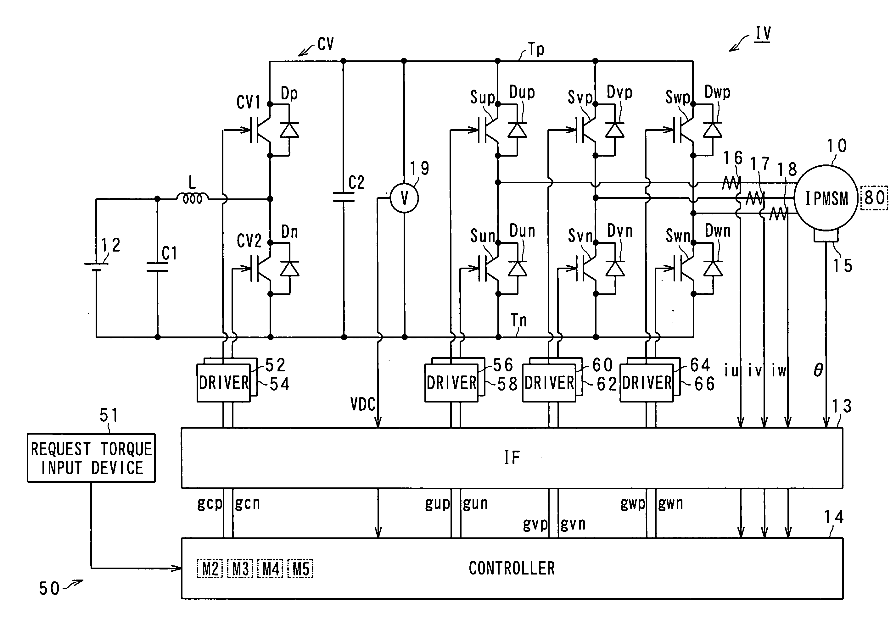
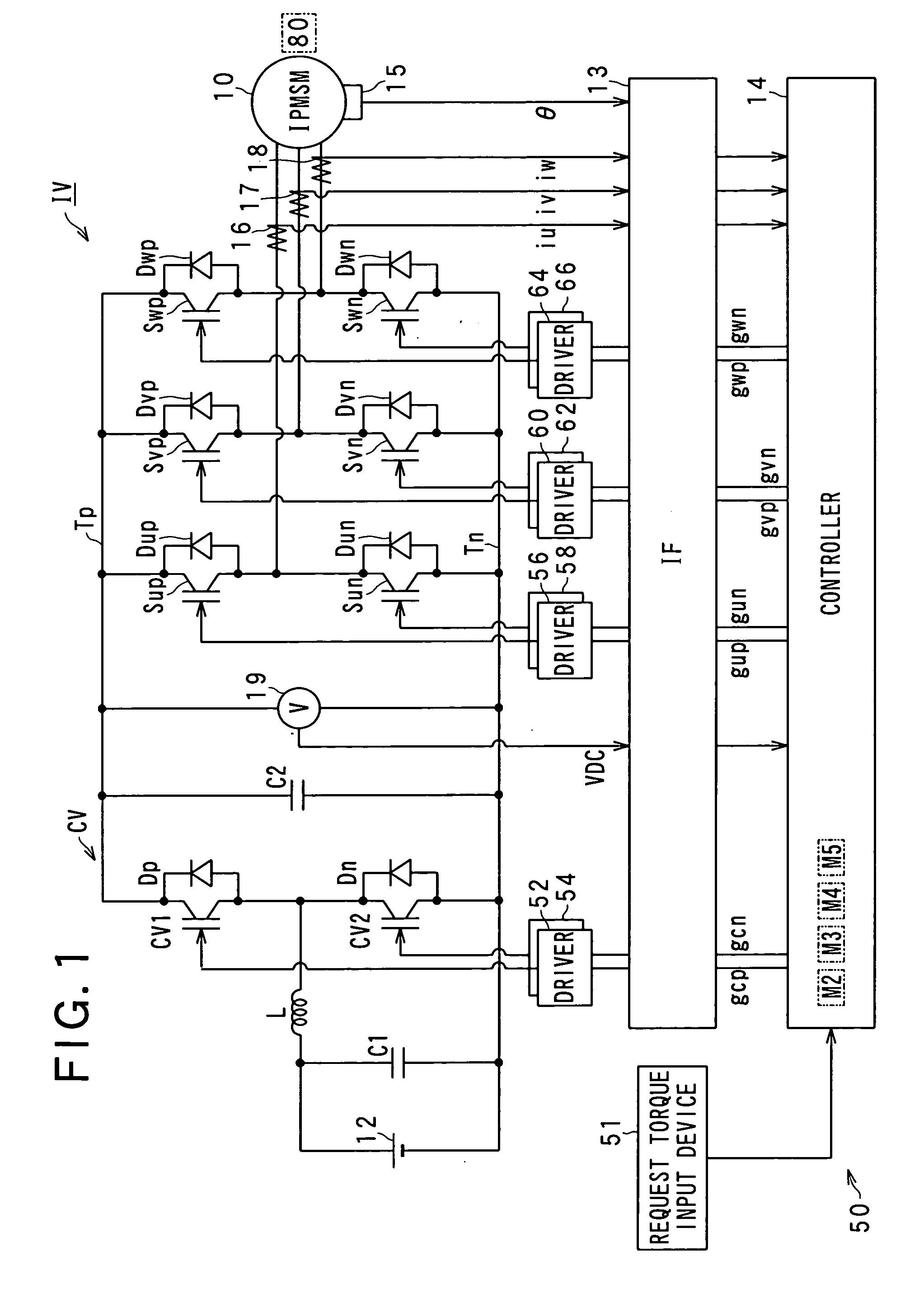
[0048]Referring to the drawings, in which like reference characters refer to like parts in several figures, particularly to FIG. 1, there is illustrated a three-phase motor-generator, referred to simply as “motor-generator (MG)”10 installed in a hybrid vehicle. In the first embodiment, as the motor-generator 10, a salient-pole motor having a salient-pole structure is used. For example, as the motor-generator 10, an IPMSM (Interior Permanent Magnet Synchronous Motor) is used.

[0049]In FIG. 1, there is also illustrated a control system 50. The control system 50 is equipped with an inverter IV serving as a power converter, a voltage converter CV, a high-voltage battery 12, an interface 13, a control apparatus 14, and gate drivers 52, 54, 56, 58, 60, 62, 64, and 66.

[0050]Specifically, the motor-generator 10 and the high-voltage battery 12 can establish electrical connection therebetween via the inverter IV and the voltage converter CV.

[0051]For example, the motor-generator 10 is provided...

second embodiment

[0228]A control system according to the second embodiment of the present invention will be described hereinafter with reference to FIGS. 9 and 10.

[0229]The structure of the control system according to the second embodiment is substantially identical to that of the control system 50 according to the first embodiment except for the following different points. So, like parts between the control systems according to the first and second embodiments, to which like reference characters are assigned, are omitted or simplified in description.

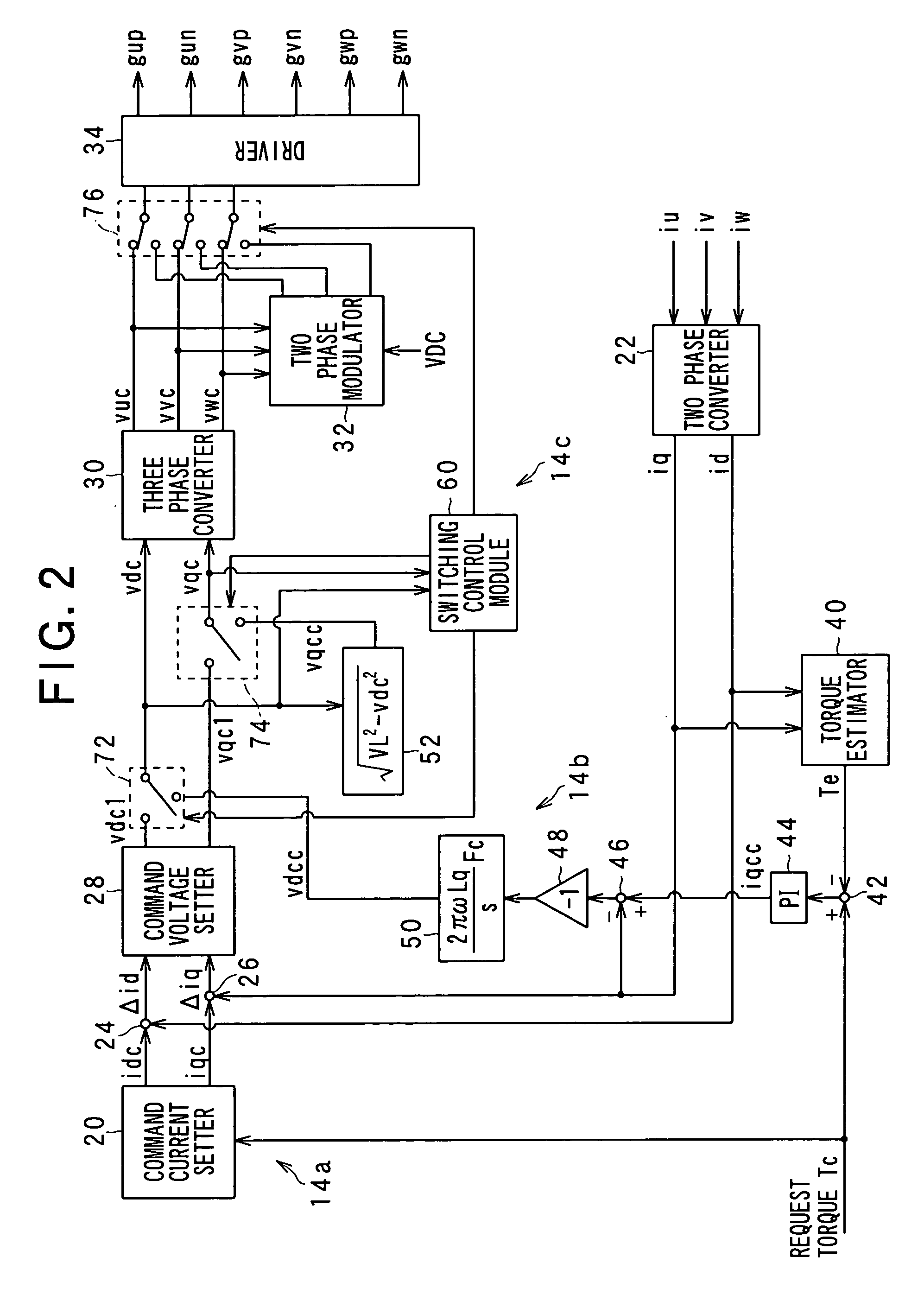
[0230]The control system 50 according to the first embodiment is designed to estimate the command voltages vdce and vqce in accordance with a model defined by the voltage equation [c1] in order to generate, by the vector control, a torque generated by the field weakening control. However, the model is changed with change in the operating state of the motor-generator 10. For example, the inductances Ld and the Lq are changed with change in a magnetic fie...

third embodiment

[0259]A control system according to the third embodiment of the present invention will be described hereinafter with reference to FIG. 11.

[0260]The structure of the control system according to the third embodiment is substantially identical to that of the control system according to the second embodiment except for the following different points. So, like parts between the control systems according to the second and third embodiments, to which like reference characters are assigned, are omitted or simplified in description.

[0261]A fourth switching routine from the field weakening control to the vector control will be described hereinafter with reference to FIG. 11. The fourth switching routine is, for example, programmed in the controller 14 to be repeatedly executed thereby at a preset cycle during execution of the field weakening control. Note that like operations between the third and fourth switching routines, to which like reference characters are assigned, are omitted or simpl...


PUM


Abstract

In an apparatus, a first drive unit drives, in a first range of a voltage utilization factor, a switching member to thereby control an output voltage of the power converter to be matched with a command voltage. A second drive unit drives, in a second range of the voltage utilization factor, the switching member to thereby generate a value of a controlled variable of a rotary machine. The second range of the voltage utilization factor is higher than the first range thereof. An estimating unit estimates, during the switching member being driven by the second drive unit, a value of a parameter associated with the output voltage of the power converter. The estimated value is required for the first drive unit to generate the value of the controlled variable generated by the second drive unit.

Description

CROSS REFERENCE TO RELATED APPLICATIONS[0001]This application is based on Japanese Patent Application 2008-166385 filed on Jun. 25, 2008. This application claims the benefit of priority from the Japanese Patent Application, so that the descriptions of which are all incorporated herein by reference.FIELD OF THE INVENTION[0002]The present invention relates to apparatuses for driving a power converter having a switching element and operative to establish electrical connection between a terminal of a rotary machine and a DC (Direct Current) power supply unit therethrough to thereby control at least one controlled variable of the rotary machine.BACKGROUND OF THE INVENTION[0003]A type of such control apparatuses set forth above is designed to carry out current feedback control to thereby adjust an actual value of at least one controlled variable of a rotary machine to a request value thereof. A typical control apparatus of this type operates in a PWM (Pulse Width Modulation) control mode ...

Claims


Application Information

Patent Timeline
Patent Type & Authority Applications(United States)
IPC IPC(8): H02P6/08H02P6/06H02P6/28H02P21/00H02P21/13H02P21/14H02P21/18H02P21/22H02P21/24H02P23/14H02P27/04H02P27/08
CPCB60L15/025Y02T10/643H02P21/0089B60L2260/44H02P21/00Y02T10/64
Inventor IMURA, AKIHIRO
Owner DENSO CORP
Why Eureka
Try Eureka