

Vehicle motor control apparatus
- Summary
- Abstract
- Description
- Claims
- Application Information
AI Technical Summary
Benefits of technology
Problems solved by technology
Method used
Image

Examples
embodiment 1
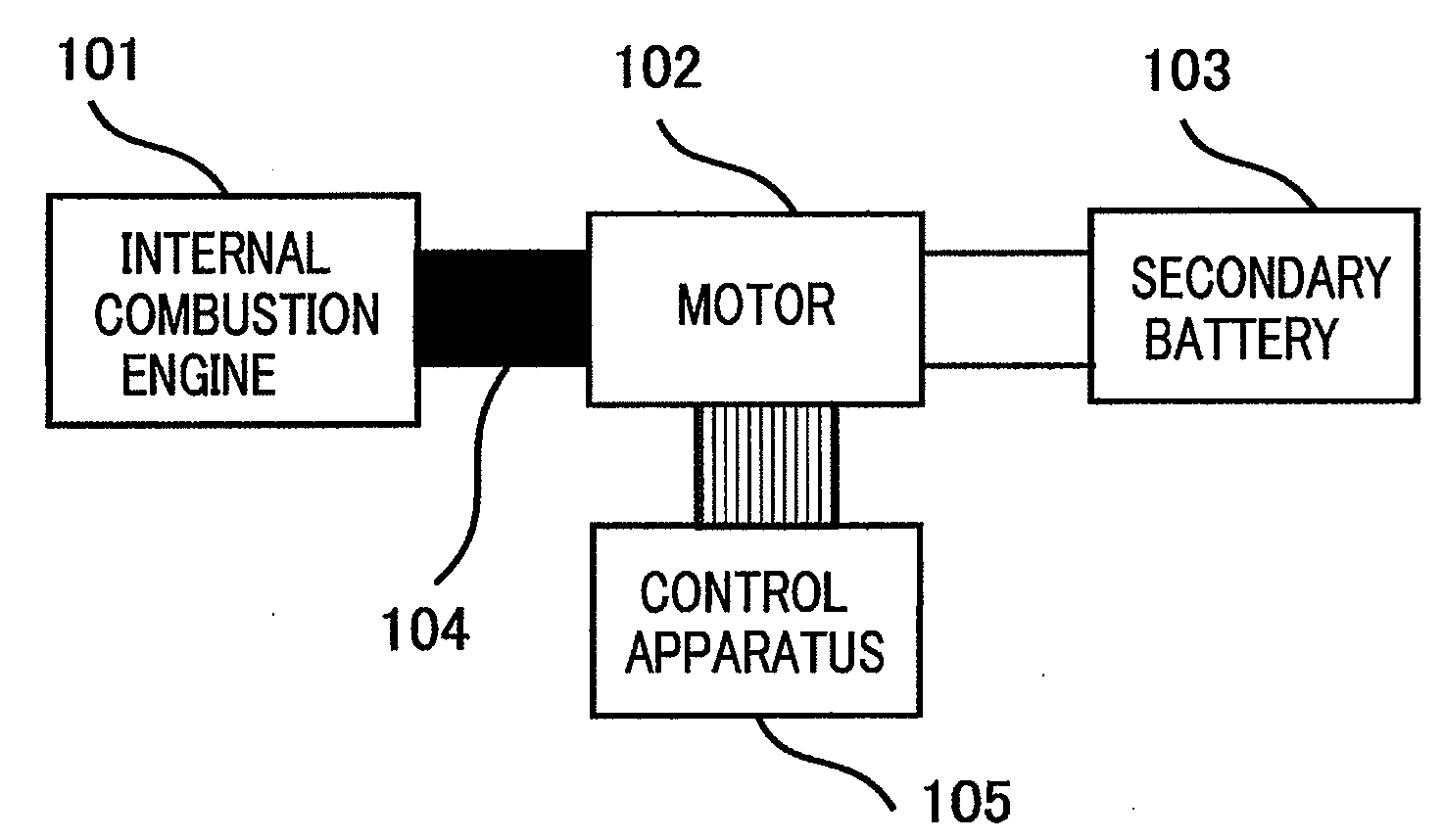
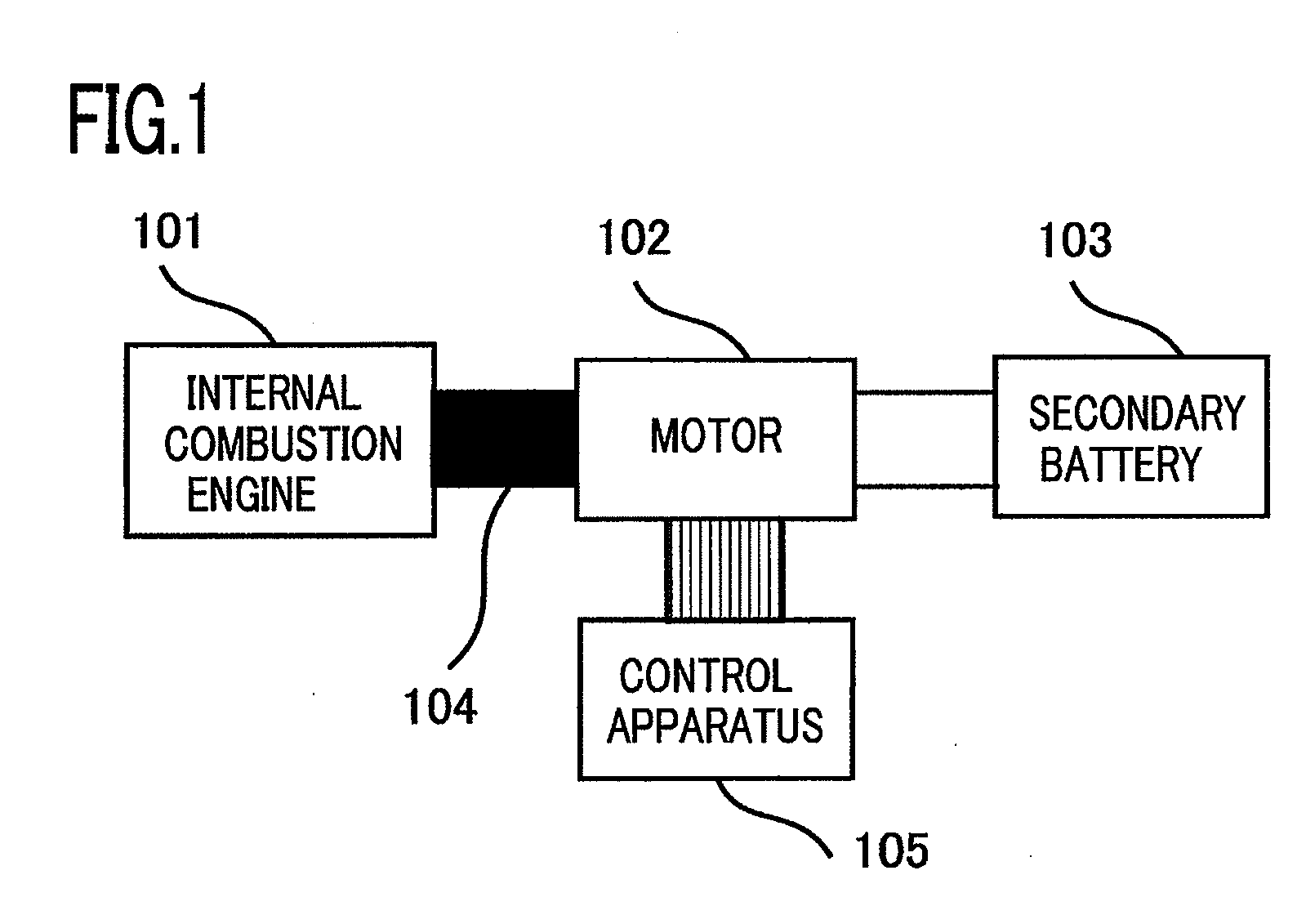
[0019]FIG. 1 is a conceptual configuration diagram in the case where a vehicle motor control apparatus or a power-generation motor control apparatus according to Embodiment 1 of the present invention is applied to a vehicle. In FIG. 1, reference numeral 101 denotes an internal combustion engine such as a gasoline engine or a diesel engine; reference numeral 102 denotes a motor that is coupled with the internal combustion engine 101 directly or via a coupling means 104 such as a belt or a pulley and disposed in such a way as to be able to transfer torque to and receive torque from the internal combustion engine 101; reference numeral 103 denotes a secondary battery that is electrically connected to the motor 102; the secondary battery 103 may be a secondary battery that is utilized also for other vehicle loads or a secondary battery dedicated to the motor 102. The secondary battery 103 may be a capacitor, and the motor 102 may be a power-generation motor. Reference numeral 105 is a c...
PUM
 Abstract
Description
Claims
Application Information