Non-isolated current-mode-controlled switching voltage regulator

a voltage regulator and current mode technology, applied in the field of voltage regulators, can solve the problems of noise and ripple in output, inferior vfm control to its counterpart, less efficient pwm control in power consumption,

Inactive Publication Date: 2009-12-31
RICOH ELECTRONIC DEVICES CO LTD
View PDF4 Cites 71 Cited by
  • Summary
  • Abstract
  • Description
  • Claims
  • Application Information

AI Technical Summary

Benefits of technology

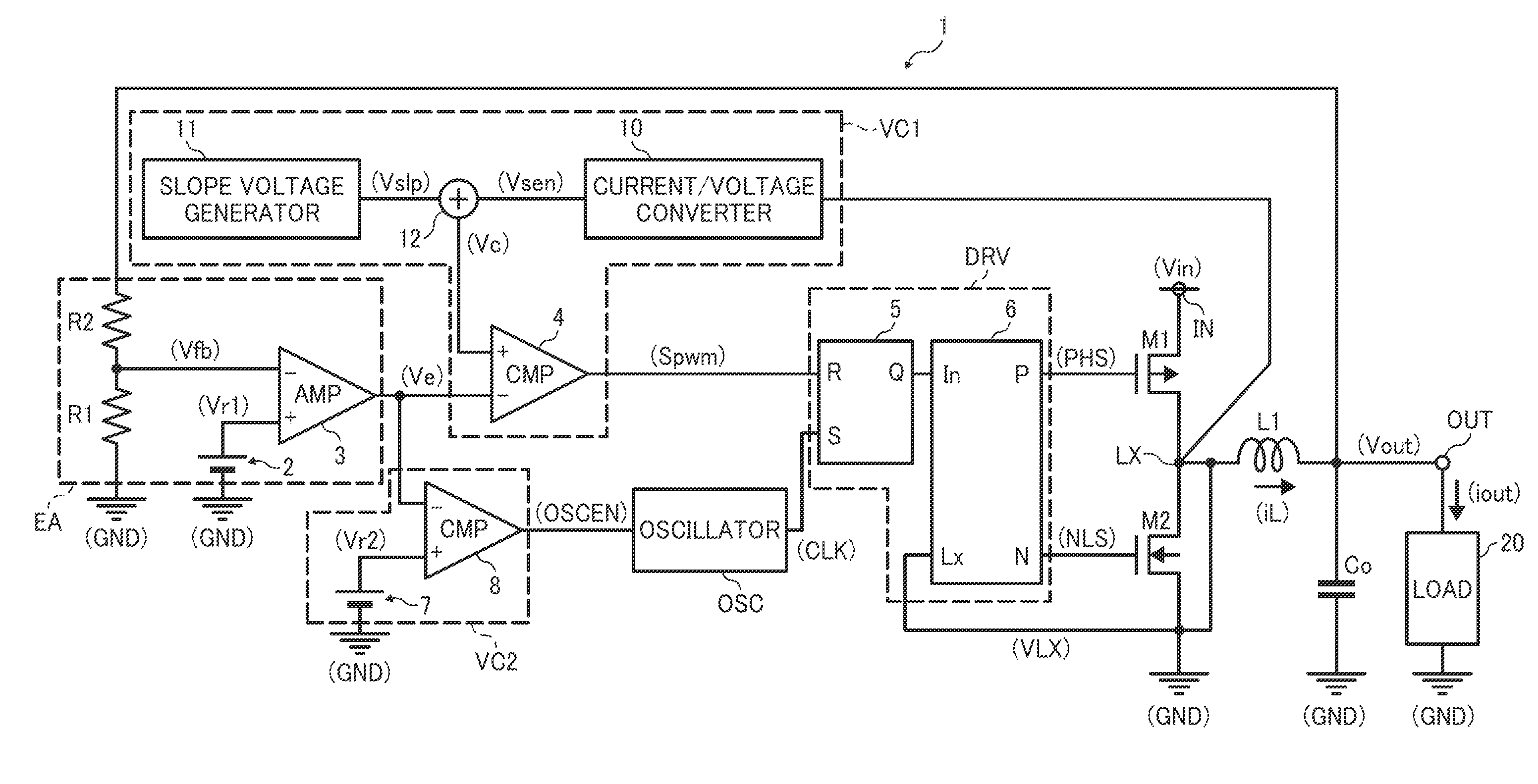
[0046]This disclosure describes a novel non-isolated current-mode-controlled switching voltage regulator that converts a voltage input to an input terminal to output a constant voltage to an output terminal while switching control mode between PWM mode and VFM mode depending on a current output to the output terminal.
[0047]In one aspect of the disclosure, the novel voltage regulator includes an indictor, a switching transistor, a rectifier, an error amplifier circuit, a first voltage comparator circuit, a second voltage comparator circuit, an oscillator circuit, and a driver circuit. The inductor is connected between the input terminal and the output terminal. The switching transistor charges the inductor with the input voltage by switching on and off according to a switching control signal. The rectifier discharges the inductor when the switching transistor switches off. The error amplifier circuit amplifies a difference between a first reference voltage and a feedback voltage proportional to the output voltage, and outputs an error voltage indicating the amplified voltage difference. The first voltage comparator circuit compares the error voltage against a ramp voltage generated by adding a slope compensation voltage to a current-sensing voltage corresponding to a current f

Problems solved by technology

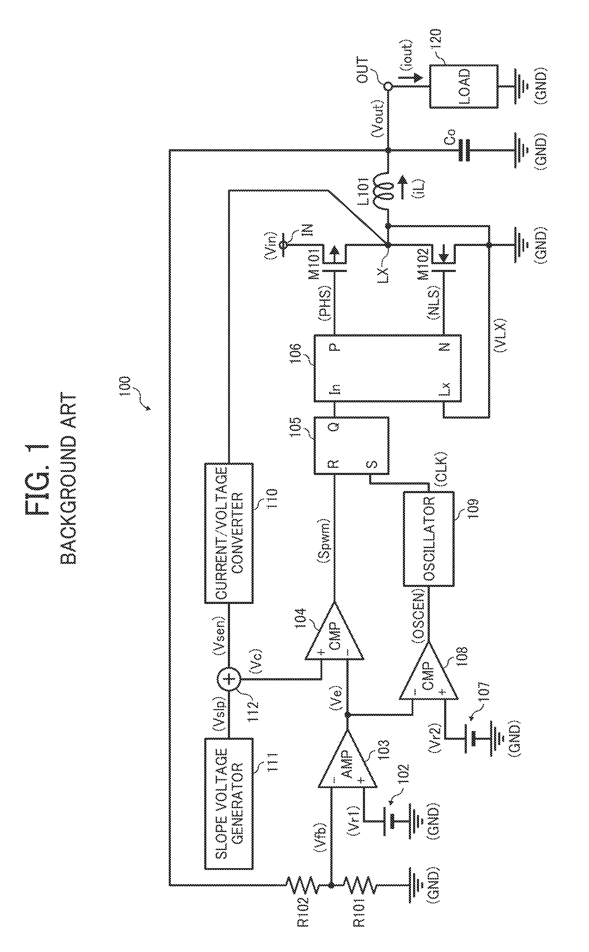
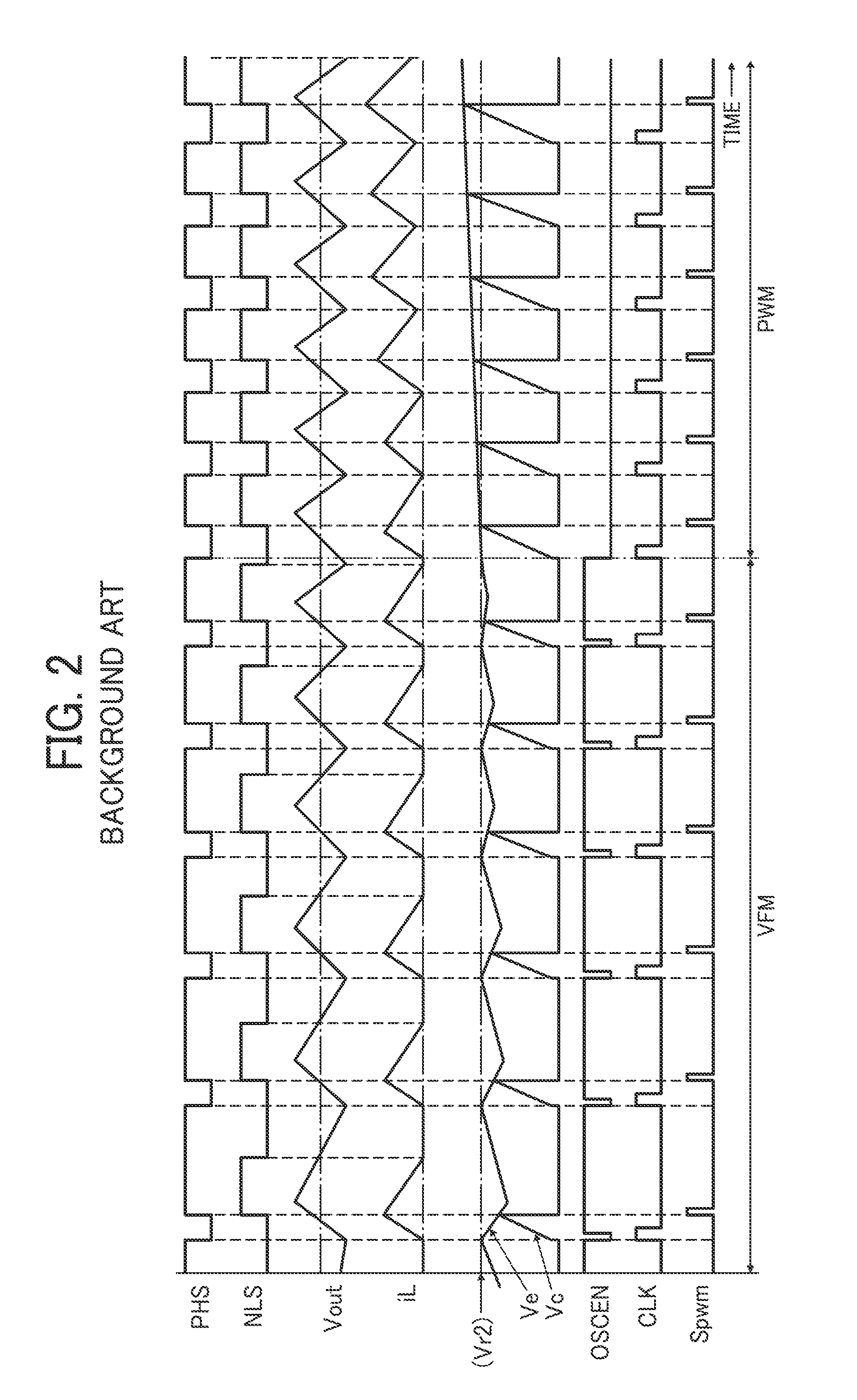
The fact indicates that with low power supplied to load circuitry, PWM control is less efficient in terms of power consumption than VFM control, since the former constantly switches the output transistor at a fixed frequency whereas the latter can adjust the switching frequency to decrease corresponding to the low-load condition.
On the other hand, VFM control is inferior to its counterpart in terms of operational stability, for varying the switching frequency can cause noise and ripple in the output of the voltage regulator.
On the other hand, the smaller the output current iout, the slower the output voltage Vout decreases, resulting in a longer period of time during which the switching transistor M101 remains off.
In this case, switching control mode from VFM to PWM abruptly raises the switching frequency of the transistor M101 and hence the energy supplied to the inductor L101, resulting in a steep surge in the output voltage Vout.
In this case, whil

Method used


Image

  • Non-isolated current-mode-controlled switching voltage regulator
  • Non-isolated current-mode-controlled switching voltage regulator
  • Non-isolated current-mode-controlled switching voltage regulator

Examples


Embodiment Construction

[0056]In describing exemplary embodiments illustrated in the drawings, specific terminology is employed for the sake of clarity. However, the disclosure of this patent specification is not intended to be limited to the specific terminology so selected, and it is to be understood that each specific element includes all technical equivalents that operate in a similar manner and achieve a similar result.

[0057]Referring now to the drawings, wherein like reference numerals designate identical or corresponding parts throughout the several views, examples and exemplary embodiments of this disclosure are described.

[0058]FIG. 4 is a circuit diagram illustrating a non-isolated current-mode-controlled switching voltage regulator 1 according to one embodiment of this patent specification.

[0059]As shown in FIG. 4, the voltage regulator 1 is configured as a step-down or buck DC-DC converter with synchronous rectification, which converts a voltage Vin input to an input terminal IN to output a cons...


PUM


Abstract

A novel voltage regulator includes an indictor, a switching transistor, a rectifier, an error amplifier circuit, a first voltage comparator circuit, a second voltage comparator circuit, an oscillator circuit, and a driver circuit. The first voltage comparator circuit outputs a modulation signal. The second voltage comparator circuit activates an enable signal when the error voltage exceeds the second reference voltage. The oscillator circuit outputs a clock signal with a fixed frequency according to the enable signal. The oscillator circuit enters a first state when the enable signal is activated and deactivated within a period of time shorter than a threshold time, and enters a second state when the enable signal remains activated during a period of time longer than the threshold time. The driver circuit generates the switching control signal based on the clock signal and the modulation signal.

Description

BACKGROUND OF THE INVENTION[0001]1. Technical Field[0002]The present invention relates to a voltage regulator, and more particularly, to a non-isolated current-mode-controlled switching voltage regulator that regulates an input DC voltage to output a constant DC voltage while switching control mode between PWM mode and VFM mode depending on a current output to load circuitry.[0003]2. Discussion of the Background[0004]With currently increasing concern for environmental and ecological issues, there is a growing need for energy-saving electronic devices, particularly those operating with battery-based power supply. Two common approaches to conserving energy in electronic equipment are to reduce power consumed by functional units of the electronic device, and to improve efficiency and reduce energy loss of power circuitry supplying the electronic device.[0005]A non-isolated switching voltage regulator is an example of a high-efficiency power source used in small portable electronic devi...

Claims


Application Information

Patent Timeline
IPC IPC(8): G05F1/00
CPCH02M3/156
Inventor MICHISHITA, YUUSUKESHIMIZU, SHINYA
Owner RICOH ELECTRONIC DEVICES CO LTD
Why Eureka
Try Eureka