In-vehicle wireless system

a wireless system and vehicle technology, applied in the field of wireless systems, can solve the problems of degrading performance, affecting the operation of vehicles with more than one remote controller, and affecting the maintenance so as to achieve the effect of increasing the maintenance efficiency of the in-vehicle wireless system

Inactive Publication Date: 2009-12-31
TOYOTA BOSHOKU KK
View PDF21 Cites 7 Cited by
  • Summary
  • Abstract
  • Description
  • Claims
  • Application Information

AI Technical Summary

Benefits of technology

[0028]To counter the above problems, the present invention is to provide a highly-reliable in-vehicle wireless system that certainly receives a wireless signal transmitted from a remote control transmitter, copies the control code, and transmits high-frequency wireless signals to control garage door opening-closing mechanisms or the like in such a manner that the high-frequency wireless signal is certainly received.

Problems solved by technology

However, having more than one remote controller and operating the remote controllers separately from one another in a vehicle is not convenient to users.
In cases where such transmitters and receivers are used, the accuracy and stability of the frequencies are poorer, and the performances are degraded due to environmental changes such as temperature changes and deterioration caused with time.
In some cases, there is the problem of a decrease in the distance over which transmission can be performed between a transmitter and a receiver.
As a result, the high-frequency transmission circuit and reception circuit and the control method become complicated.
Secondly, the frequency characteristics and the likes of the receivers provided in garage door opening-closing mechanisms and the likes and the remote control transmitter are often unstable or frequencies of the wireless signals may be inaccurate, as described above.
Furthermore, the radio waves to be received might be affected by fading, noise, or the like in some electromagnetic environment in the surrounding area.
In those cases, reception becomes difficult, and the transmission distance becomes shorter.

Method used


Image

  • In-vehicle wireless system
  • In-vehicle wireless system
  • In-vehicle wireless system

Examples


first embodiment

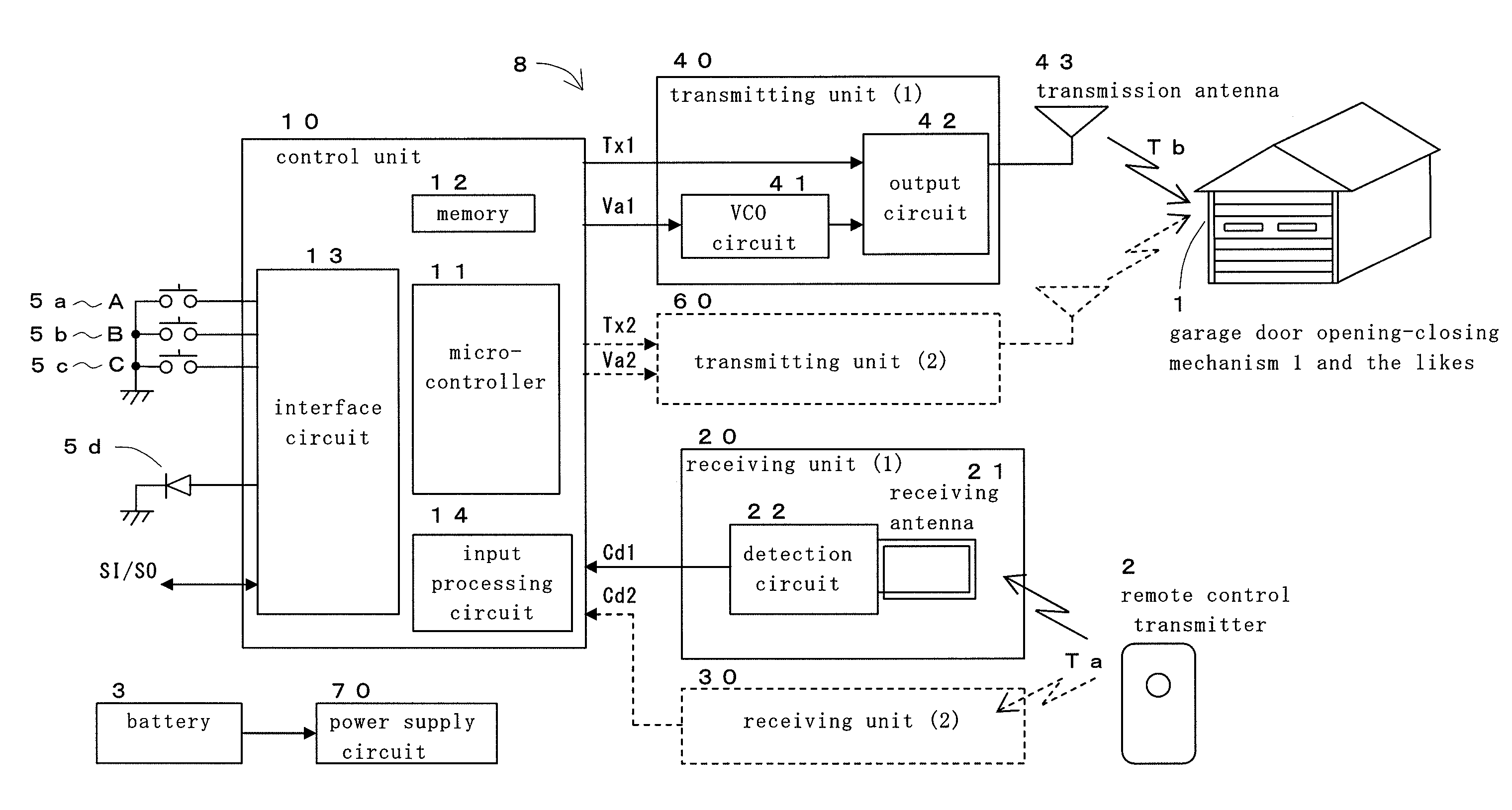
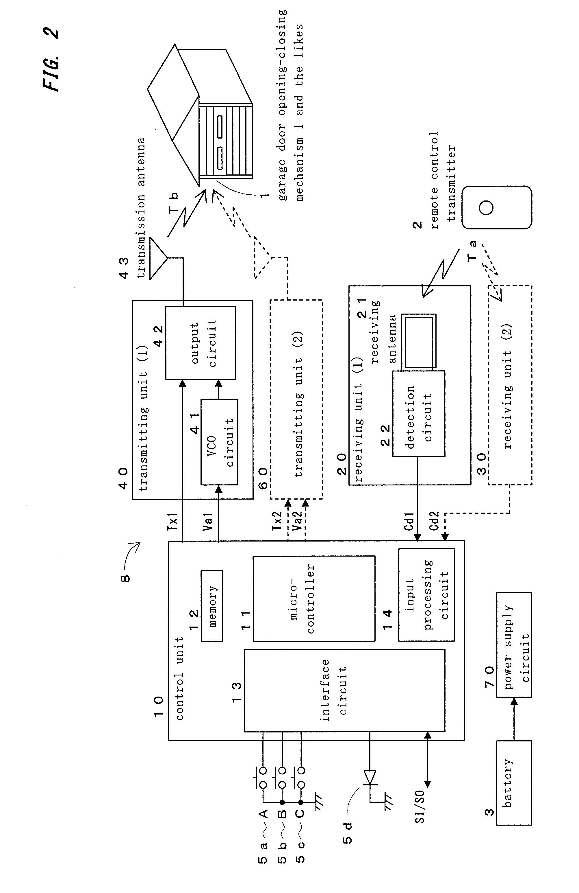
[0179]FIG. 10 is a circuit diagram showing a specific example design of the receiving unit 20. This receiving unit 20 includes the reception antenna 21, diodes 221 and 222, the operational amplifier 223, the comparator 224, and peripheral devices.

[0180]The reception antenna 21 is a coil-like loop antenna. Each high-frequency signal received by this antenna is detected by the high-frequency diode 221. Since the forward voltage of a high-frequency diode greatly varies with temperature, temperature compensating is performed with the use of the high-frequency diode 222, as mentioned above. The detected signal is amplified by the operational amplifier 223, and is binarized and shaped by the comparator 224. The signal is then output as the control code signal Cd1.

[0181]To increase the sensitivity of the receiving unit 20, an amplifier circuit and a bandpass filter that filters signals in the target frequency band may be provided between the reception antenna 21 and the detection circuit.

[...

second embodiment

[0183]FIG. 11 is a circuit diagram showing a specific design example of the transmitting unit 40. This transmitting unit includes a PWM signal smoothing circuit 41a, the VCO circuit 41, the PLL circuit 44, the ASK modulation circuit 45, the amplifier circuit 46, and the transmission antenna 43.

[0184]The PWM signal (PWM-A1) that is output from the microcontroller 11 of the control unit 10 is smoothed by the smoothing circuit 41a. The capacitance of the variable capacitance diode 411 varies with the voltage generated at this point, and the oscillation frequency of the VCO circuit 41 changes.

[0185]The output of the VCO circuit 41 is input to the PLL circuit 44 via a buffer circuit 412.

[0186]The PLL circuit 44 includes a phase comparator 442, a low-pass filter 444, a voltage controlled oscillator circuit 443, and a divider 441 that divides the frequency of each input signal by 32. The PLL circuit 44 generates a signal of a frequency 32 times higher than the frequency of the signal that ...

third embodiment

[0189]FIG. 12 shows an example arrangement of transmission antennas for performing diversity transmission. Two loop antennas 431 and 432 are placed at a distance from each other and perpendicularly to each other on a substrate 430, so as to provide spatial diversity. The positions of the feeding points of the respective antennas can be differentiated from each other so as to differentiate the polarizations of the transmission waves sent from the respective antennas.


PUM


Abstract

An in-vehicle wireless system, capable of operating at least in a copy mode and a transmission mode, comprises: at least one receiving unit receiving a wireless signal transmitted from a remote control transmitter and demodulates a control code signal; and at least one transmitting unit transmitting wireless signals at a plurality of carrier frequencies; and a control unit controlling so as to obtain a control code from the control code signal and store it in the copy mode, and so as to perform transmitting the modulated wireless signals at all carrier frequencies unique to a plurality of the garage door opening-closing mechanisms or the like. The receiving unit may include a detection circuit connected to a reception antenna directly.

Description

CROSS-REFERENCE TO RELATED APPLICATIONS[0001]The present application claims priority under 35 U.S.C. §119 of Japanese Patent Application No. 2008-171474, filed on Jun. 30, 2008, the disclosure of which is expressly incorporated by reference herein in its entirety.BACKGROUND OF THE INVENTION[0002]1. Field of the Invention[0003]The present invention relates to a wireless system to be mounted on a vehicle, and more particularly, to an in-vehicle wireless system that receives and copies high-frequency wireless signals from transmitters that remotely control garage door opening-closing mechanisms, household equipments, and the likes, and transmits high-frequency wireless signals for operating the garage door opening-closing mechanisms and the likes.[0004]2. Description of the Related Art[0005]As remote controllers for controlling various household electric equipments and devices from a distance have widely spread, universal remote controllers that can remotely control devices and equipme...

Claims


Application Information

Patent Timeline
Patent Type & Authority Applications(United States)
IPC IPC(8): G08B29/00E04H6/42H04B1/3822H04B1/40H04B5/02H04B7/06H04B7/08H04B7/10H04B7/12H04Q9/00
CPCH04B7/0602H04B7/10H04B7/0817
Inventor UNO, HIDEKITODA, SHIGEYOSHI
Owner TOYOTA BOSHOKU KK
Why Eureka
Try Eureka