Passive and active photonic crystal structures and devices

a photonic crystal and passive technology, applied in the field of passive active photonic crystal structures and devices, can solve the problems of high optical throughput and low loss, and inability to achieve high optical throughput and low loss, and achieve the effect of modulating the intensity of the input optical beam

Active Publication Date: 2009-12-31
THE BOARD OF TRUSTEES OF THE UNIV OF ILLINOIS
View PDF78 Cites 75 Cited by
  • Summary
  • Abstract
  • Description
  • Claims
  • Application Information

AI Technical Summary

Benefits of technology

[0039]In another aspect, the present invention provides a method for modulating the intensity of an input optical beam having a frequency distribution comprising the steps of: (1) directing the input optical beam onto a photonic crystal having a photonic band gap with a tunable frequency distribution comprising a dielectric structure having a spatial distribution of refractive indices that varies periodically in at least one dimension, the dielectric structure comprising alternating high refractive index elements and low refractive index elements provided in a periodic spatial configuration; the low refractive index elements or the high refractive index elements comprising a photodynamic polymer exhibiting a selectively variable refractive index that changes upon exposure to an excitation a beam of polarized electromagnetic radiation; and (2) changing the frequency distribution of the photonic band gap of the photonic crystal by exposing the photonic crystal to the excitation a beam of polarized electromagnetic radiation, thereby modulating the intensity of the input optical beam. Optionally, the periodic spatial configuration of alternating high refractive index elements and low refractive index elements of the dynamic photo...

Problems solved by technology

While these approaches have met with some degree of success, tunable photonic crystals currently do not exhibit the high level of performance (e.g., fast modulation rate, high optical t...

Method used


Image

  • Passive and active photonic crystal structures and devices
  • Passive and active photonic crystal structures and devices
  • Passive and active photonic crystal structures and devices

Examples


example 1

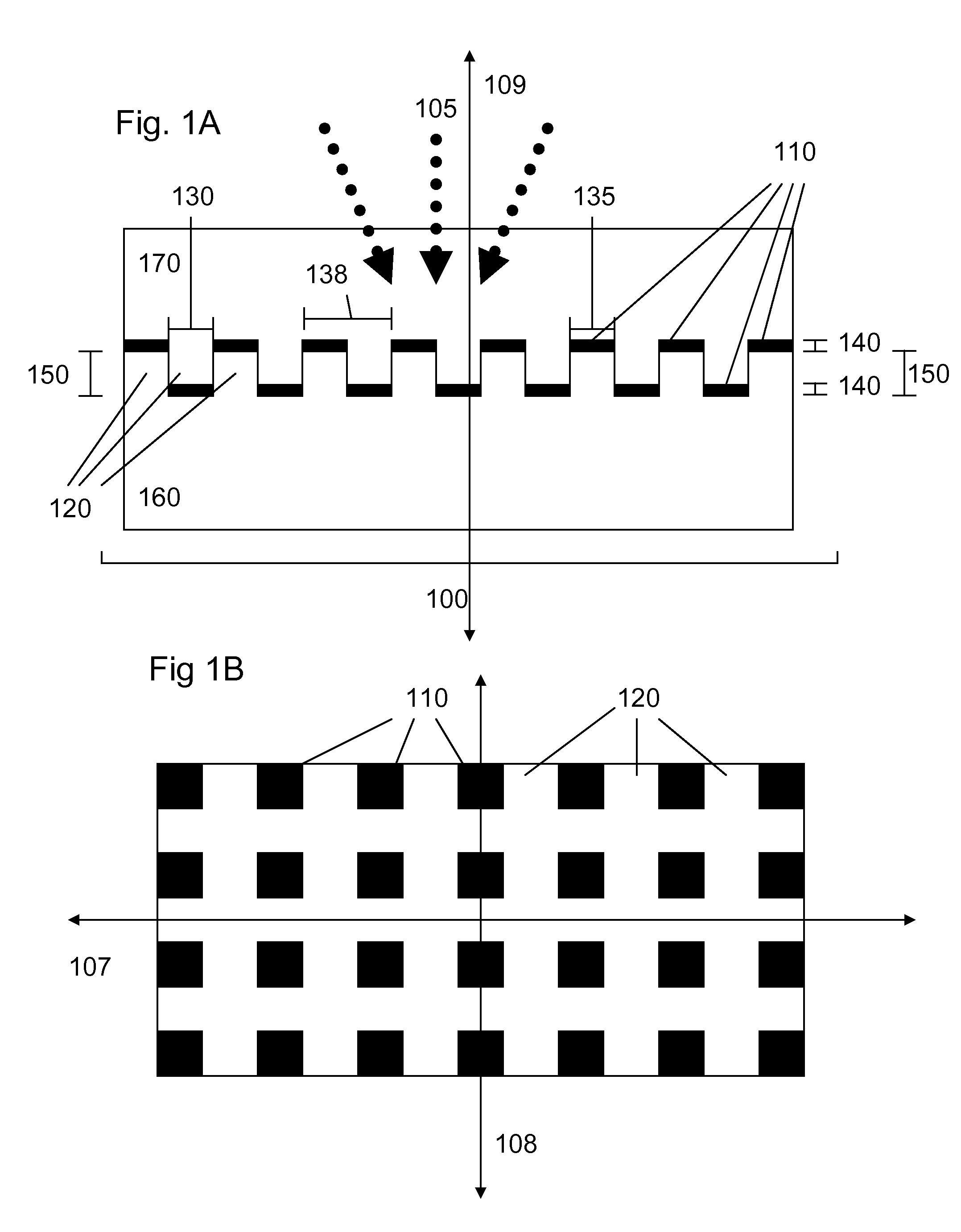
Photonic Crystal Wavelength-Selective Tunable Filters for Laser Eye Shielding

1.A Summary of Technical Objectives

[0132]The rapid development of laser technology has made portable laser systems with high power and energy widely available for applications in communication, scientific research, and manufacturing. Unfortunately, these laser systems have also been employed as a means for disabling soldiers and weapon systems by inflicting damage to human eyes and photosensors. Therefore, the development of countermeasures that can limit the effectiveness of laser weapons against these targets is an important area of research. The goal of certain embodiments of the present invention is to develop of laser eye shielding technology that is capable of reflecting particular wavelengths of laser light with nearly 100% efficiency while still enabling the soldier to see out from the shield at other wavelengths. Additionally, the laser eye shield should be capable of rapidly responding to the thre...

example 2

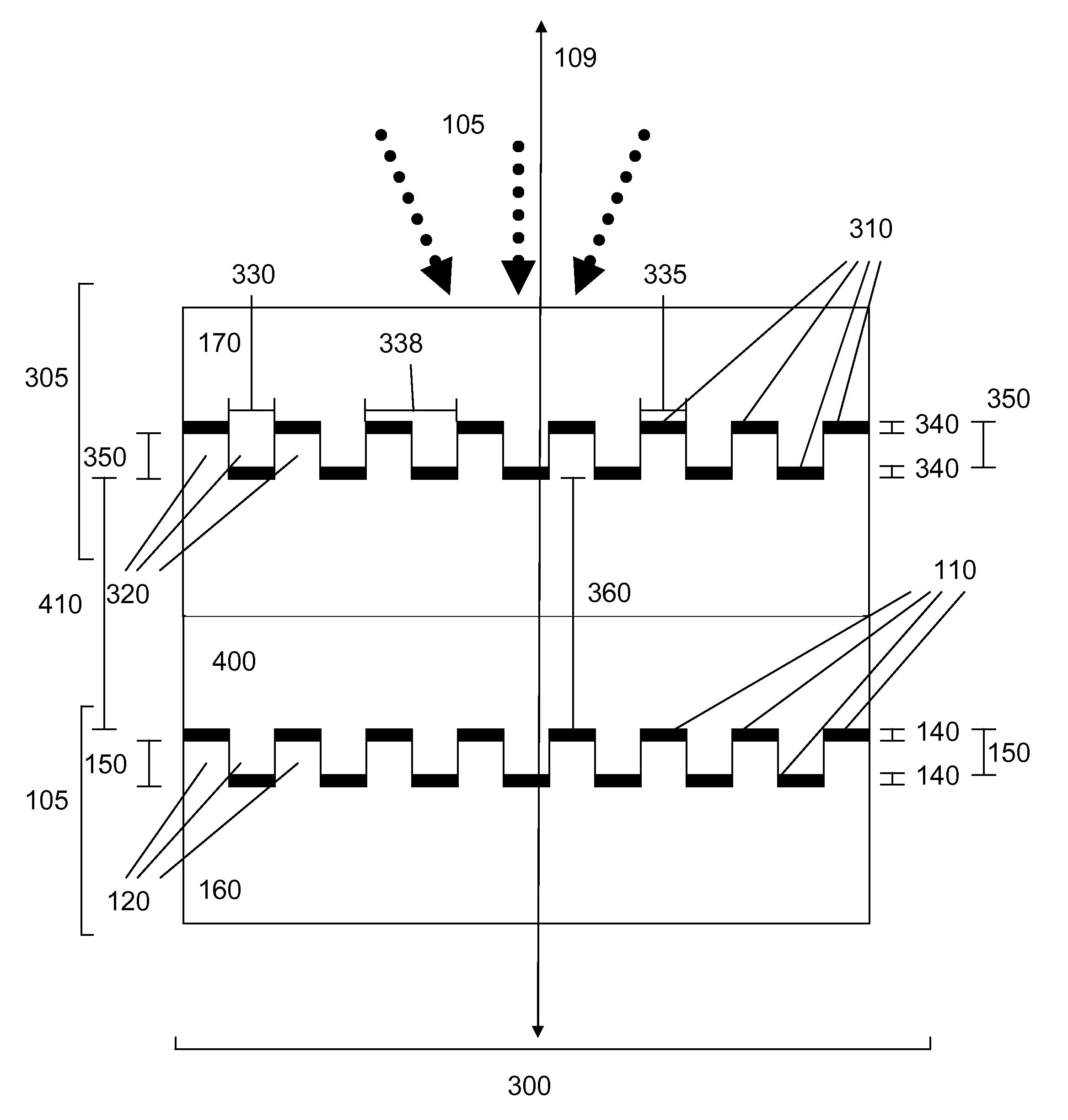
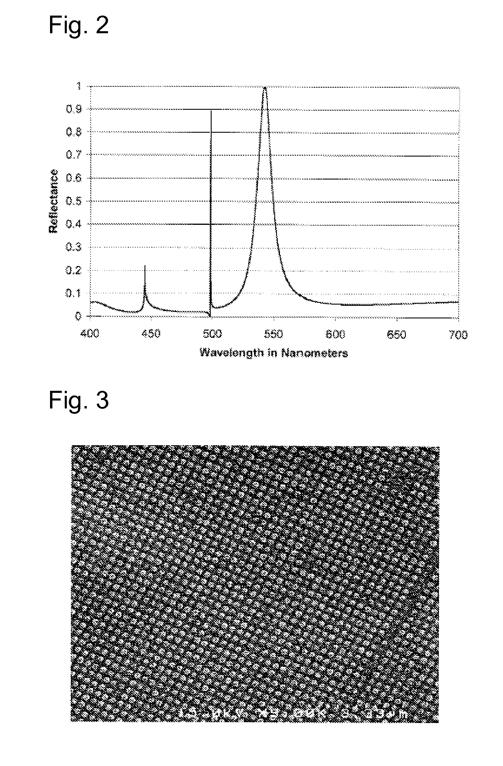
Optically Tunable Photonic Crystal Reflectance Filter

[0155]It is an objective of the present invention to provide dynamic photonic crystals having a tunable photonic band gap with a selectively adjustable frequency distribution. In this example, we demonstrate a photonic crystal structure whose properties are tunable with laser illumination through the incorporation of a nonlinear dye. Laser illumination causes a change in the bulk refractive index of the dye-doped portion of the structure, leading to controlled tuning of the photonic crystal reflectance spectrum. Changes in the refractive index of dye-doped regions are proportional to the intensity of the incident laser beam, and are as high as Δn=0.09. The reflectance tuning effect is completely reversible upon termination of laser illumination.

2.A. Introduction

[0156]The nonlinear optical properties of azobenzene dyes have been extensively studied in recent years. These materials are very attractive due to the fact that large chan...


PUM


Abstract

The present invention provides photonic crystal devices, device components and methods for preventing transmission of electromagnetic radiation from one or more laser sources or laser modes so as to provide an optical shield for protecting a users eyes or an optical sensor. The present invention also provides dynamic photonic crystals and devices incorporating dynamic photonic crystals for optically modulating the intensity of one or more beams of electromagnetic radiation and other optical switching applications.

Description

CROSS REFERENCE TO RELATED APPLICATIONS[0001]This application claims priority under 35 U.S.C. 119(e) to U.S. provisional Patent Application 60 / 782,565 filed Mar. 15, 2006, which is hereby incorporated by reference in its entirety.STATEMENT REGARDING FEDERALLY SPONSORED RESEARCH OR DEVELOPMENT[0002]This invention was made with United States government support awarded by Battelle under contract number TCN 04174, a subcontract under the U.S. Army Research Office contract DAAD19-02-D-0001.BACKGROUND OF THE INVENTION[0003]Photonic crystals, also commonly referred to as photonic bandgap structures, are periodic dielectric or metallic structures exhibiting a spatially periodic variation in refractive index that forbids propagation of certain frequencies of incident electromagnetic radiation. The photonic band gap of a photonic crystal refers to the range of frequencies of electromagnetic radiation for which propagation through the structure is prevented. The photonic band gap phenomenon ma...

Claims


Application Information

Patent Timeline
IPC IPC(8): G02C7/10G02B5/28G02F1/01
CPCA61F9/022G02B5/28G02F2202/32G02F2201/30G02F2202/022G02C7/107G02B1/005
Inventor CUNNINGHAM, BRIAN T.DOBBS, DENNIS W.
Owner THE BOARD OF TRUSTEES OF THE UNIV OF ILLINOIS
Why Eureka
Try Eureka