Electric power conversion device, compressor motor with the device, and air conditioner with the motor

a technology of electric power conversion and compressor motor, which is applied in the direction of motor/generator/converter stopper, electronic commutator, dynamo-electric converter control, etc., can solve the problems of large change in load condition, inability to apply method in association with current detection accuracy, and difficulty in application of method to a usage. , to achieve the effect of safe electric power conversion devi

Inactive Publication Date: 2009-12-31
HITACHI LTD +1
View PDF12 Cites 28 Cited by
  • Summary
  • Abstract
  • Description
  • Claims
  • Application Information

AI Technical Summary

Benefits of technology

[0020]An advantage obtained by the present invention is that the wire breaking detection can be surely performed regardless to such as an amount of current command value and operating conditions of the electric power conversion device as well as during the operation thereof.
[0021]Further, according to the present invention, since the wire breaking detection can be performed by the electric power conversion device itself without relying on a superior system, a further safe electric power conversion device can be realized.

Problems solved by technology

Namely, it is difficult to apply the method to a usage where the load condition greatly changes.
Further, since the judgment is performed based on the amount of current variation, the method cannot be applied in association with current detection accuracy under a condition when a certain amount of current is flowing.
Still further, the method cannot judge which phase in the motor windings is wire broken.
However, if a wire either in V phase or in W phase is broken, since a current flows through a route in the other phase, in this instance the wire breaking detection with this current route fails.
In other words, the wire breaking detection cannot be performed during the operation of the motor.
Further, since the wire breaking detection has to be performed by successively changing the switching state, it is difficult to apply the method to an application that requires, for example, to start a motor in a short time.
As has been explained above, problems of the conventional methods of detecting the motor phase current and of providing the operating state used for the wire breaking detection prior to starting are such as necessity of the current flowing of a certain amount, the limited application conditions and the incapability of wire breaking detection during operation.
Further, the technology disclosed in patent document 3, is for a method of detecting wire breaking only under a certain condition, therefore, the wire breaking detection therewith cannot be performed without regarding operating conditions.

Method used


Image

  • Electric power conversion device, compressor motor with the device, and air conditioner with the motor
  • Electric power conversion device, compressor motor with the device, and air conditioner with the motor
  • Electric power conversion device, compressor motor with the device, and air conditioner with the motor

Examples


embodiment 1

[0046]The present embodiment will be explained while using a motor as the load.

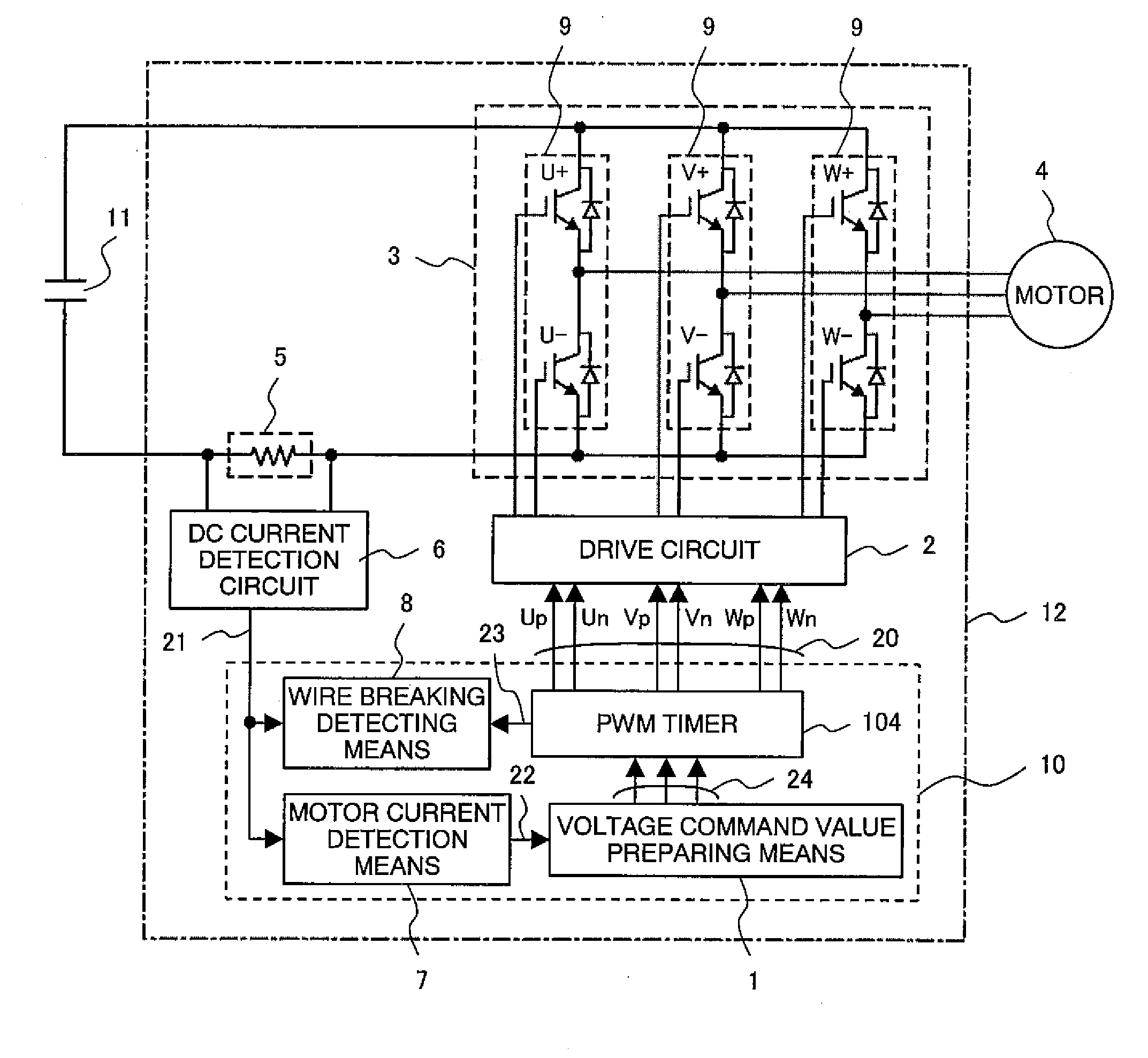
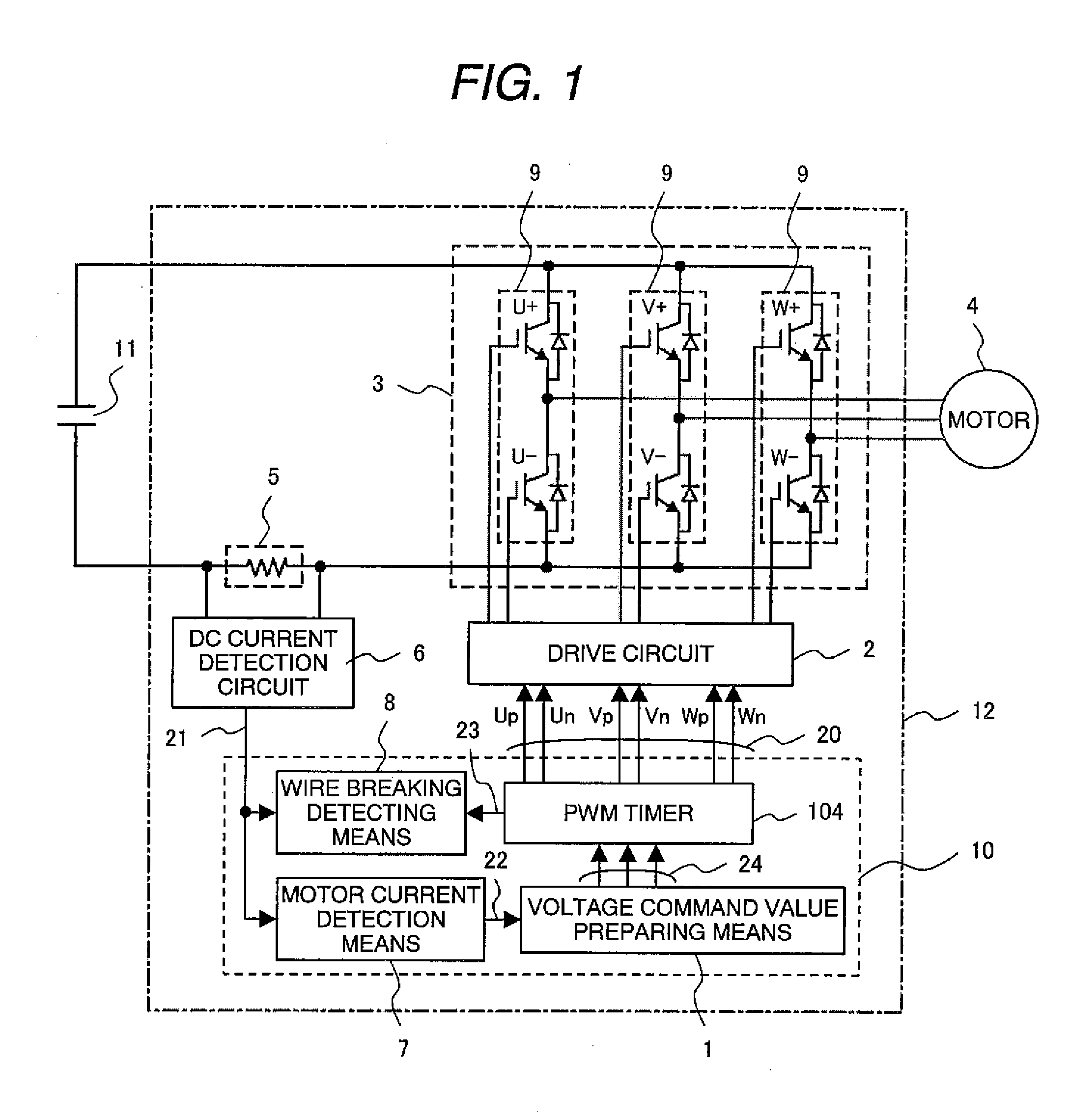
[0047]At first, embodiment 1 of an electric power conversion device according to the present invention will be explained. In FIG. 1, a general constitutional diagram of a motor drive device serving as the electric power conversion device is shown. The motor drive device (electric power conversion device) 12 is configured by an inverter circuit (electric power conversion circuit) 3 constituted by switching elements 9, a shunt resistor 5, a voltage command value preparing means 1, a PWM pulse generating unit 104, a DC current detecting circuit 6, a motor current detecting means 7, a wire breaking detecting means 8 and a drive circuit 2. Further, the voltage command value preparing means 7, the PWM pulse generating unit 104, the motor current detecting means 7 and the wire breaking detecting means 8 can be accommodated in a single control circuit 10 by such as a microcomputer and a DSP (Digital Signal Proces...

embodiment 2

[0070]An operation after detecting a wire breaking will be explained with reference to from FIG. 8 to FIG. 10 in connection with embodiment 2 of an electric conversion device (motor drive device) according to the present invention. A wire breaking detection means 208 in the present embodiment is the same as embodiment 1 with regard to the wire breaking detection method, but different because the wire breaking detection means 208 outputs a wire breaking detection signal 201 after detecting a wire breaking. The wire breaking detection signal 201 is input to an angular frequency command adjusting means 202 (stop controlling means or deceleration and stop controlling means) as well as to a PWM pulse generation unit 204 as shown in FIG. 8. The angular frequency command adjusting means 202 decreases an angular frequency command value when the wire breaking detection signal 201 is input.

[0071]When there are no problems if a motor is suddenly stopped, as shown in FIG. 9(a), at the same time...

embodiment 3

[0073]An embodiment 3 of an electric power conversion device according to the present invention will be explained with reference to FIG. 11. The electric power conversion device of the present embodiment is constituted as a module while accommodating the motor drive device 12 in the single package. The device is constituted while roughly being divided into twp parts, in that a power portion (the inverter circuit 3 and the shunt resistor 5) accommodated in a lower package 300 and a subsubstrate 317 carrying the control circuit 10, the DC current detection circuit 6 and the drive circuit 2 as shown in FIG. 11. In the drawing, although the lower package 300 and the subsubstrate 317 are illustrated separately for the sake of easy explanation, actually both are integrated. In the lower package 300, an aluminum substrate 301 is disposed on which such as the switching elements 9 and the shunt resistor 5 are mounted. The DC voltage source 11 is input from terminals 305b and an AC power is o...


PUM


Abstract

The device is provided with an electric power conversion circuit including switching elements for converting a DC electric power to an AC electric power, a load connected to an output side of the electric power conversion circuit, means for detecting a current flowing through a DC side in the electric power conversion circuit, a voltage command value preparing means for controlling the operation of the switching elements in the electric power conversion circuit and a wire breaking detecting means. The wire breaking detection means judges a wire breaking in the load or an abnormality of any of the switching elements in the electric power conversion circuit by making use of a DC current detection value in a period when a current of maximum voltage phase or of voltage minimum phase of the electric power conversion circuit is flowing in a DC current.

Description

CLAIM OF PRIORITY[0001]The present application claims priority from Japanese patent application serial no. 2008-168039, filed on Jun. 27, 2008, the content of which is hereby incorporated by reference into this application.FIELD OF THE INVENTION[0002]The present invention relates to an electric power conversion device having an electric power conversion circuit that is controlled by pulse width modulation signals (PWM signals) and in particular concerns to an effective technology applicable to a wire breaking detection in a load connected to an output side of an electric power conversion circuit.BACKGROUND ART[0003]As methods of detecting wire breaking, variety methods thereof have been proposed hitherto, for example, such as a method of performing a wire breaking detection by detecting a phase current in a load (motor) and a method of performing a wire breaking detection while providing an operating state used for the wire breaking detection prior to starting a motor.[0004]As the a...

Claims


Application Information

Patent Timeline
Patent Type & Authority Applications(United States)
IPC IPC(8): H02H3/00H02M7/537
CPCH02M1/32H02M2001/0009H02M7/5395H02M7/53873H02M1/0009
Inventor SUZUKI, TAKAHIRONOTOHARA, YASUOSAKAMOTO, KIYOSHI
Owner HITACHI LTD
Why Eureka
Try Eureka