
Read-time wear-leveling method in storage system using flash memory device

a technology of flash memory and read-leveling, which is applied in the direction of digital storage, instruments, computing, etc., can solve the problems of poor reliability of flash memory devices that are a storage system, and the limitations of flash devices that are currently commercially used a lot, so as to prolong the life improve the reliability of flash memory devices, and reduce the effect of operation errors of flash memory devices caused by partial abrasion

Inactive Publication Date: 2009-12-31
SANOCHEMIA PHARMA AG +1
View PDF4 Cites 38 Cited by
  • Summary
  • Abstract
  • Description
  • Claims
  • Application Information

AI Technical Summary

Benefits of technology

[0009]The present invention has been made in view of the above problems, and the present invention provides a read-time wear-leveling method in which the abrasion of a flash memory device caused by repeatedly performing read operations on data stored in the flash memory device is dispersed over the entire region so that the abrasion of memory blocks can be equalized to prolong the life of the flash memory device and to minimize operation errors in the memory blocks.
[0012]As described above, according to the present invention, the abrasion of a logic memory block, which is generated during the read operation of a flash memory device, is divisionally mapped to a physical memory block so that the abrasion is equalized over the entire memory block and that the life of the flash memory device can be prolonged.
[0013]In addition, according to the present invention, since the abrasion of the flash memory device is equalized, the operation errors of the flash memory device caused by partial abrasion can be reduced so that the reliability of the flash memory device can be improved.

Problems solved by technology

In the flash memory device, the NAND flash device that is currently commercially used a lot commonly has limitations on the number of times of repeating write / erase operations of about 10,000 to 100,000 per block (the minimum operation unit when the flash memory device is driven).
In addition, due to the abrasion, the memory blocks generate frequent errors so that the reliability of the flash memory device that is a storage system is poor.

Method used

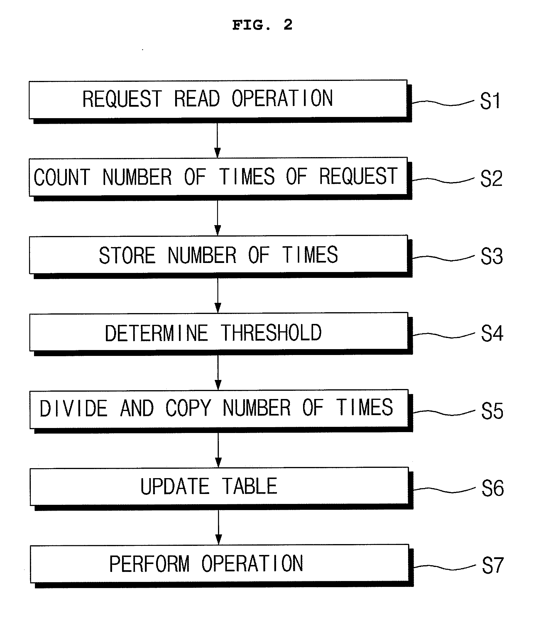

Image

  • Read-time wear-leveling method in storage system using flash memory device
  • Read-time wear-leveling method in storage system using flash memory device
  • Read-time wear-leveling method in storage system using flash memory device

Examples


Embodiment Construction

[0017]Hereinafter, an embodiment of the present invention will be described in detail with reference to the accompanying drawings.

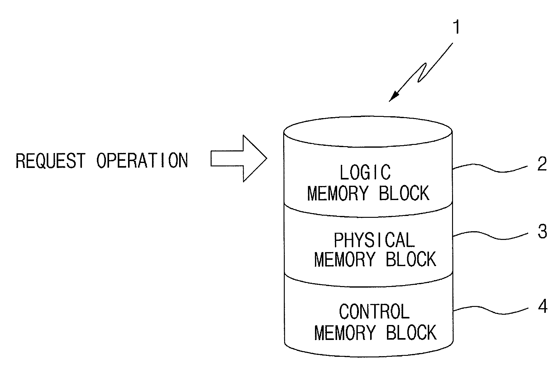
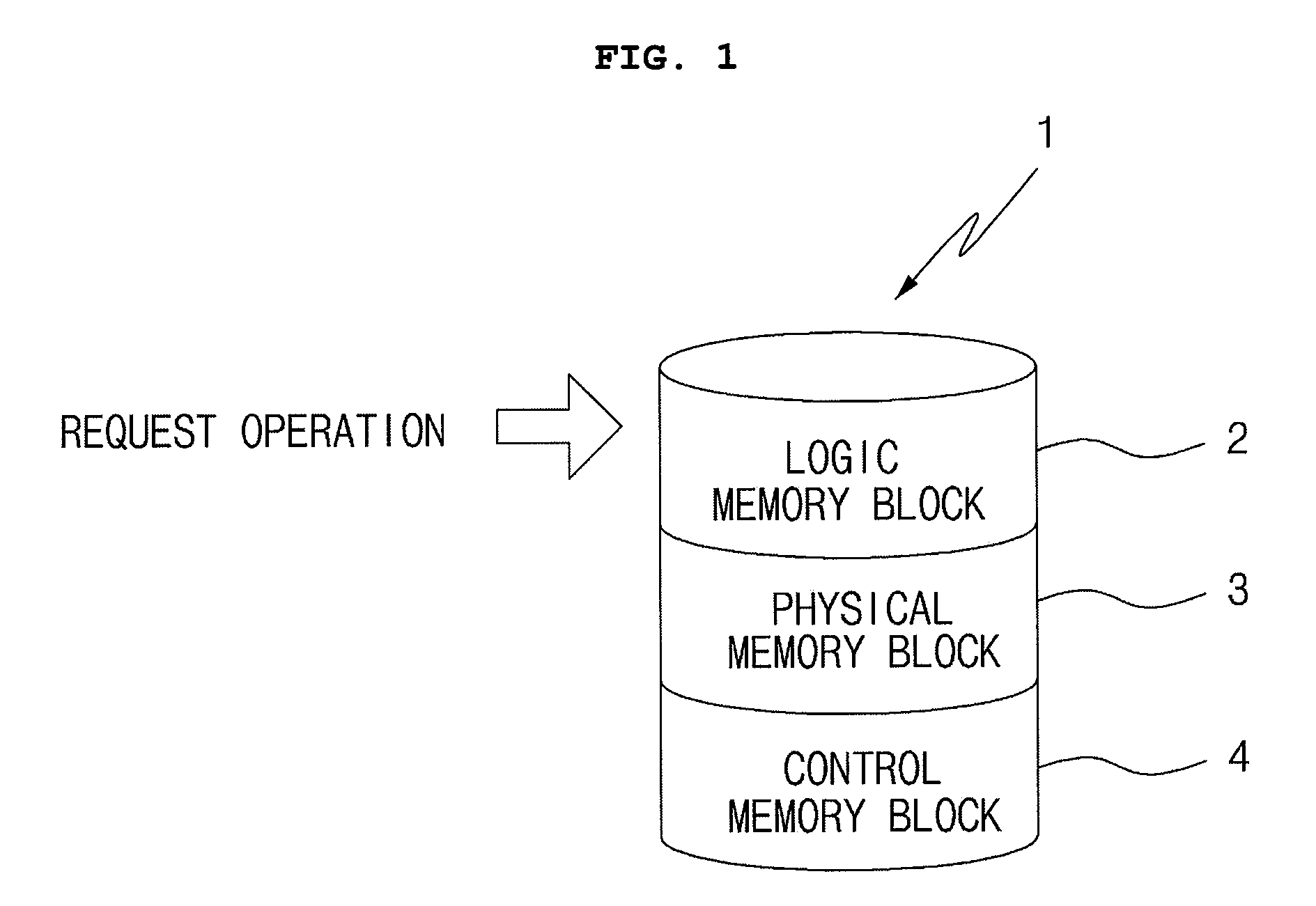
[0018]FIG. 1 is a block diagram illustrating performance of a read-time wear-leveling method according to an embodiment of the present invention.

[0019]Referring to the drawing, in order to perform read-time wear-leveling according to an embodiment of the present invention, a memory cell 1 is divided into a logic memory block 2, a physical memory block 3, and a control memory block 4.

[0020]The memory cell 1 becomes a space in which the respective memory blocks 2, 3, and 4 exist and various processors such as a central processing unit (CPU) operating a memory are connected to the memory cell 1. In addition, the number of each block is only one in the drawing. However, it is well-known that each block may be divided into a plurality of regions no less than 2 and that addresses may be assigned to the divided blocks, respectively.

[0021]The logic memory block 2...


PUM


Abstract

Disclosed is a read-time wear-leveling method in a storage system using a flash memory device, in which the abrasion of the flash memory device generated by repeated read operations is dispersed over the entire region so that the abrasion of memory blocks can be equalized to prolong the life of the flash memory device, to minimize errors in the memory blocks, and to secure the reliability of the storage system.

Description

BACKGROUND OF THE INVENTION[0001]1. Field of the Invention[0002]The present invention relates to a read-time wear-leveling method in a storage system using a flash memory device, and more particularly to, a read-time wear-leveling method in a storage system using a flash memory device, in which the abrasion of a flash memory device caused by repeated read operations is dispersed over the entire region so that the abrasion equalization of memory blocks can be maintained to prolong the life of the flash memory device, to minimize errors in the memory blocks, and to secure the reliability of the storage system.[0003]2. Description of the Related Art[0004]A flash memory device is a non-volatile memory device having low power consumption and a characteristic in that stored information is not lost although power is intercepted. In particular, it is well-known that, since information is freely input to and output from the flash memory device, the flash memory device is widely used for a di...

Claims


Application Information

Patent Timeline
IPC IPC(8): G11C16/04
CPCG06F12/0246G11C16/349G06F2212/7211G06F2212/1032
Inventor LEE, JOO-HYEONGSHIN, KI-YEONG
Owner SANOCHEMIA PHARMA AG
Learn More