
Fiber optic shape sensor

a fiber optic and shape sensor technology, applied in the field of shape sensing, can solve the problems of limited 3d point resolution, fbg size limits the measurement resolution, and disadvantages of current optical fiber shape sensing methods, and achieve the effect of convenient calculation

Active Publication Date: 2009-12-31
INTUITIVE SURGICAL OPERATIONS INC
View PDF40 Cites 242 Cited by
  • Summary
  • Abstract
  • Description
  • Claims
  • Application Information

AI Technical Summary

Benefits of technology

[0012]As the joints move, an interrogator senses strain in the shape sensing segment. The sensed strain is used to output a Cartesian position and orientation of the end of the shape sensing segment with respect to the reference frame defined at the start of the shape sensing segment. The Cartesian position and orientation may be used to define a reference frame for a subsequent shape sensing segment for one or more additional links and joints in the kinematic chain. The Cartesian position and orientation is determined and output in a format that facilitates calculation. The pose of the kinematic chain is determined from the Cartesian positions and orientations of one or more shape sensing segments defined for the kinematic chain, from an a priori model of the kinematic chain, and from the geometrical constraints between the shape sensing fiber and the kinematic chain.

Problems solved by technology

There are, however, disadvantages to current optical fiber shape sensing methods.
To begin with, such methods are based on the average strain measured in each FBG, and so the FBG size limits the measurement resolution.
Also, the resolution of the 3D points is limited by the spacing between FBG's.
Further, in these methods there is an assumption that the length of fiber between measured FBG's has a constant bend radius, and this assumption can reduce the accuracy of the sensed shape as compared with the fiber's actual shape.
Another disadvantage is that the computation of the fiber tangent vector at a particular fiber location (i.e., the direction the fiber is pointing at that location) requires differentiation of the 3D points.
Yet another disadvantage is that the 3D point data set is not in a form that is required for the type of processing needed when the fiber is embedded into a kinematic chain, and therefore the kinematic chain's pose has to be inferred from the sensed fiber position.
This limitation is especially true if the fiber is embedded in a kinematic chain but is allowed to slide with reference to one or more links.

Method used


Image

  • Fiber optic shape sensor
  • Fiber optic shape sensor
  • Fiber optic shape sensor

Examples


example 1

A. EXAMPLE 1

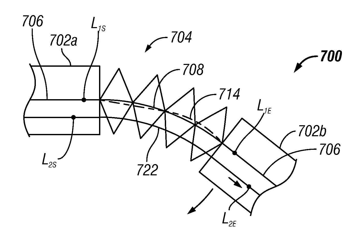
[0094]Referring to FIG. 7, a kinematic chain of four links coupled to retain two DOF's of bending can be described by an overall kinematic model:

[pktk]=ƒkin({right arrow over (q)}1,{right arrow over (q)}2)   (20)

[0095]The sensing segment start frame is defined in the first link, and the sensing segment end frame is defined in the second link. The three cases of the sensing fiber attached to both links, attached in the first link and unconstrained at the tip to slide in a tight cylindrical conduit in the second link, or attached in the second link and unconstrained to slide in a tight cylindrical conduit in the first link, can all be described by the goal function:

Min with respect to {right arrow over (q)}1,{right arrow over (q)}2 of {Abs(ts−tk)}  (21)

[0096]This function describes that the fiber segment end is constrained to have the same orientation with respect to the fiber segment start as the second link has with respect to the first link. Given that the orientation m...

example 2

B. EXAMPLE 2

[0097]Referring to FIG. 10, a single-DOF rotational joint {right arrow over (q)}1 can be described by the kinematic model of the form:

[pktk]=ƒkin({right arrow over (q)}1)   (22)

[0098]The sensing segment start frame is defined in the first (proximal) link, and the sensing segment end frame is defined in the second (distal) link. The sensing fiber may be attached in the first link and unconstrained to slide in a tight, cylindrical conduit in the second link, or the sensing fiber may be attached in the second link and unconstrained to slide in a tight, cylindrical conduit in the first link. The associated goal function is:

Min with respect to {right arrow over (q)}1 of {Abs(ts−tk)}  (23)

[0099]Given that the orientation measurement ts has two DOF's (it is a unit vector), {right arrow over (q)}1 is determined, and the measurement noise can be minimized too.

[0100]In another implementation, the fiber may be constrained in a slit (rather than in a cylindrical conduit) in either o...

example 3

C. EXAMPLE 3

[0101]Referring to FIG. 9A, mechanism 902 illustrates a kinematic chain of seven links and additional mechanical constraints that enforce the parallelism of the output link 906 with respect to shaft 904 so that two DOF's {right arrow over (q)}1 and {right arrow over (q)}2 are sufficient to describe the overall kinematics according to a model of the form:

[pktk]=ƒkin({right arrow over (q)}1,{right arrow over (q)}2)   (25)

[0102]The sensing segment start frame is defined in the first link (shaft 904) and the sensing segment end frame is defined in the second link (link 906). The sensing fiber may be attached in the first link and unconstrained to slide in a tight, cylindrical conduit in the second link, or the sensing fiber may be attached in the second link and unconstrained to slide in a tight, cylindrical conduit in the first link. The associated goal function that describes that the fiber end segment position with respect to the fiber start segment position in the plane ...


PUM


Abstract

A shape sensing system to determine the position and orientation of one link with respect to another link in a kinematic chain. An optical fiber is coupled to two or more links in a kinematic chain. A shape sensing segment is defined to start at a proximal link and to end at a distal link, crossing one or more joints. A reference frame is defined at the start of the shape sensing segment. As the joints move, an interrogator senses strain in the shape sensing segment. The sensed strain is used to output a Cartesian position and orientation of the end of the shape sensing segment with respect to the reference frame defined at the start of the shape sensing segment. The pose of the kinematic chain is determined from the Cartesian positions and orientations of one or more shape sensing segments defined for the kinematic chain and from an a priori model and constraints of the kinematic chain.

Description

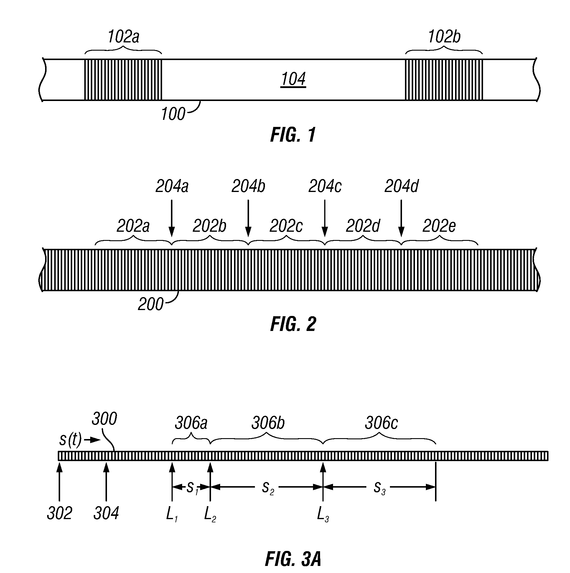
BACKGROUND[0001]1. Field of Invention[0002]Inventive aspects are associated with shape sensing, more particularly to sensing position and orientation at various points of a kinematic chain, and still more particularly to sensing the shape of a flexible body and sensing the position and orientation of an end effector component of a surgical instrument or of an entry guide for one or more surgical instruments in a telerobotic surgical system.[0003]2. Background Art[0004]FIG. 1 is a diagrammatic view of an optical fiber core portion 100. The surrounding cladding and fiber are omitted for clarity. Two fiber Bragg gratings (FBG's) 102a, 102b are shown formed in fiber core portion 100, which are illustrative of many such FBG's typically formed along the full length of a core. The many vertical lines shown in each FBG 102 represent the changes in refractive index that characterize an FBG. As shown in FIG. 1, the FBG's 102a, 102b are separated by a tether segment 104, which is completely tr...

Claims


Application Information

Patent Timeline
IPC IPC(8): G02B6/02
CPCA61B19/2203A61B2019/223A61B2019/461Y10T74/20305G01L1/246G02B6/02042A61B2019/5261A61B34/30A61B34/35A61B2090/061A61B2034/2061A61B1/009
Inventor PRISCO, GIUSEPPE
Owner INTUITIVE SURGICAL OPERATIONS INC
Learn More