Detection method of target substance, detection reagent used for the same, and the uses thereof

a detection reagent and target substance technology, applied in the field of detection methods of target substances and detection reagents used for the same, can solve the problems of difficult detection, time and cost, measurement sensitivity, etc., and achieve the effect of excellent detection accuracy and sensitivity

Inactive Publication Date: 2009-12-31
ARKRAY INC
View PDF8 Cites 9 Cited by
  • Summary
  • Abstract
  • Description
  • Claims
  • Application Information

AI Technical Summary

Benefits of technology

[0009]Hence, the present invention is intended to provide a new detection method, for detecting a target substance using formation of an aggregate due to binding o...

Problems solved by technology

However, these methods have the following problems.
That is, with respect to the former TIA method, since the obtained aggregate is small, the measurement sensitivity is insufficient.
Particularly, in a case where a concentration of a target substance in a sample is low, it is very difficult to detect.
However, such method requires plural immobilized antibodies and it takes time and cost.
However, such method takes time for optimizing dilution and dilution ratio and remeasuing.
Further, the LA method has problems of increase in background and decrease in S/N.
However, an increase in an antibody amount raises cost.
In addition, there is a limitation in performance.
In a case of the LA method, it is difficult to avoid the hook phenomenon even when the antigen-antibody ratio is set at higher level.
In a case of the TIA method, similar to the case described above, the measurement accuracy in a low concentration range is insufficient.
Therefore, when measurement of ...

Method used


Image

  • Detection method of target substance, detection reagent used for the same, and the uses thereof
  • Detection method of target substance, detection reagent used for the same, and the uses thereof
  • Detection method of target substance, detection reagent used for the same, and the uses thereof

Examples


embodiment 1

[0106]An embodiment 1 is an example of a scattered light measurement device provided with a small-diameter light source as a light source.

[0107]FIG. 8 is a perspective view of a scattered light measurement device to which a sample holding tool is provided. FIG. 9 is a cross-sectional view of FIG. 8 in the direction of A-A. FIG. 8 is a schematic view in which each component is shown separately for convenience sake. As shown in FIGS. 8 and 9, the scattered light measurement device is provided with a light source 11, a light receiving portion 16, a first light blocking portion 14, and a second light blocking portion 13. In this Embodiment, the first light blocking portion 14 is a member for blocking direct light transmitted through a sample and the second light blocking portion 13 is a member for blocking scattered light of unwanted angle transmitted through the sample. The light receiving portion 16 is disposed opposite to the light source 11. Specifically, the light receiving portion...

embodiment 2

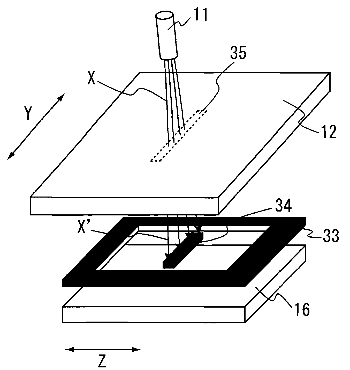
[0121]Embodiment 2 is an example of a scattered light measurement device provided with a line light source as a light source.

[0122]FIG. 10 is a perspective view of a scattered light measurement device in which a sample holding tool is provided, and is a schematic view in which each component is shown separately for convenience sake. Each component of Embodiment 2 is the same as that of the Embodiment 1 unless otherwise described.

[0123]As shown in FIG. 10, the scattered light measurement device of Embodiment 2 has the configuration similar to that of Embodiment 1 except that a light source 11 is a line light source, the planar shape of a first light blocking portion 34 and the shape of the seating rim of a second light blocking portion 33 are rectangular, and the planar shape of a sample holder 35 in a sample holding tool 12 is rectangular. In FIG. 10, an arrow Y shows a longitudinal direction and an arrow Z shows a perpendicular direction relative to the longitudinal direction.

[0124...

embodiment 3

[0143]Embodiment 3 is an example of a detection tool including a sample holder whose planar shape is circular. In this Embodiment, the sample holder may also be referred to as a light irradiating portion or a detection portion. In a case where the detection reagent is placed in the sample holder, it may be referred to as a reaction portion (hereinafter, the same applies). The detection tool of this embodiment is not particularly limited as long as it includes the light blocking portion.

[0144]FIG. 11 is a perspective view of a detection tool 40, FIG. 11A is a schematic view in which each component is shown separately for convenience sake, FIG. 11B is a perspective view viewed from the upper side of the detection tool 40, and FIG. 11C is a perspective view viewed from the back side of the detection tool 40. As shown in FIG. 11, the detection tool 40 includes a support substrate 42 and a cover substrate 41. On the surface of the support substrate 42, a channel 47 and a sample holder 45...


PUM


Abstract

A new detection method, for detecting a target substance using formation of an aggregate due to binding of a target substance and a binding substance that binds thereto, that is excellent in detection accuracy, and sensitivity, and a new detection reagent used for the same are provided. Modifying substances having a maximum diameter of about 50 nm or less bind to a binding substance that binds to a target substance, and a modified binding substance is prepared as a binding reagent. A target substance in a sample is detected by bringing this modified binding reagent into contact with the sample, and optically detecting an aggregate that is formed by binding of the modified binding substance and the target substance in the sample. Preferably, the modifying substance includes biotin or a biotin derivative and further includes avidin or an avidin derivative, and the avidin or the avidin derivative binds to the biotin or the biotin derivative. Further, preferably, the biotin or the biotin derivative binds to the binding substance via a spacer.

Description

BACKGROUND OF THE INVENTION[0001]1. Field of the Invention[0002]The present invention relates to a detection method of a target substance, a detection reagent used for the same, and the uses thereof.[0003]2. Description of Related Art[0004]As a method of detecting a target substance, a method using a binding substance which specifically bonds to the target substance is widely adopted. In this method, detection of the target substance is performed indirectly by reacting the target substance with the binding substance, confirming whether the target substance and the binding substance are bound, and measuring an amount of the binding of the target substance and the binding substance. Above all, a detection method using an antigen-antibody reaction generally is used. Typical examples thereof include a turbidimetric immunoassay (TIA) and a Latex agglutination-turbidimetric immunoassay (LA) (JP2001133454 A and JP2007315883 A). In the former TIA method, an antibody against the target subst...

Claims


Application Information

Patent Timeline
IPC IPC(8): G01N33/566G01N21/00
CPCG01N33/5306G01N21/82
Inventor HIRAI, KAORUSHIRAKI, YASUNORI
Owner ARKRAY INC
Why Eureka
Try Eureka