
Method of transmitting signaling messages

a technology of transmitting signal and message, which is applied in the field of transmitting signaling messages, can solve the problems of negative affecting the time critical applications running on the mobile terminal, and achieve the effect of reducing the delay of services to be delivered to the terminal during the handover

Active Publication Date: 2009-12-31
WSOU INVESTMENTS LLC
View PDF11 Cites 6 Cited by
  • Summary
  • Abstract
  • Description
  • Claims
  • Application Information

AI Technical Summary

Benefits of technology

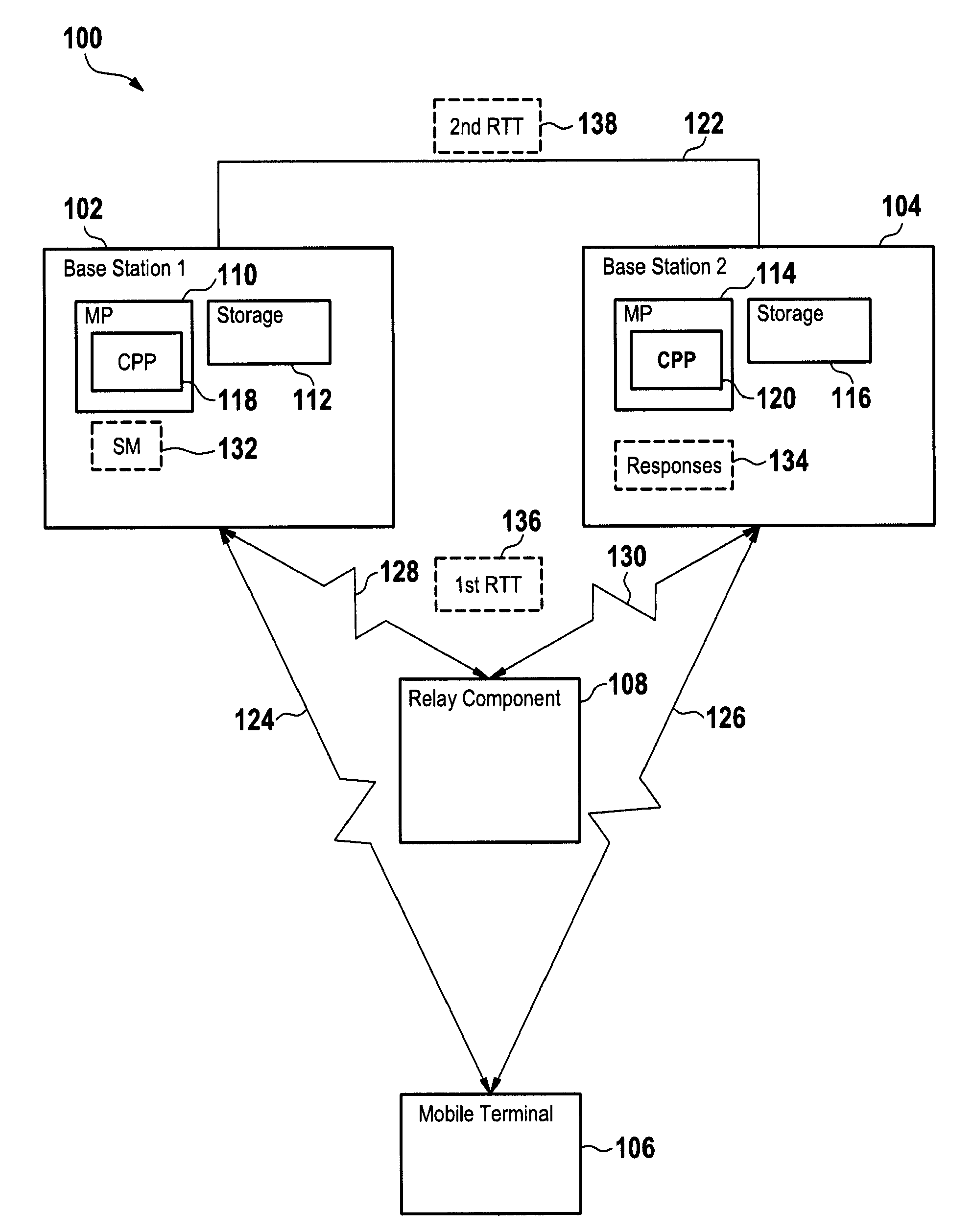
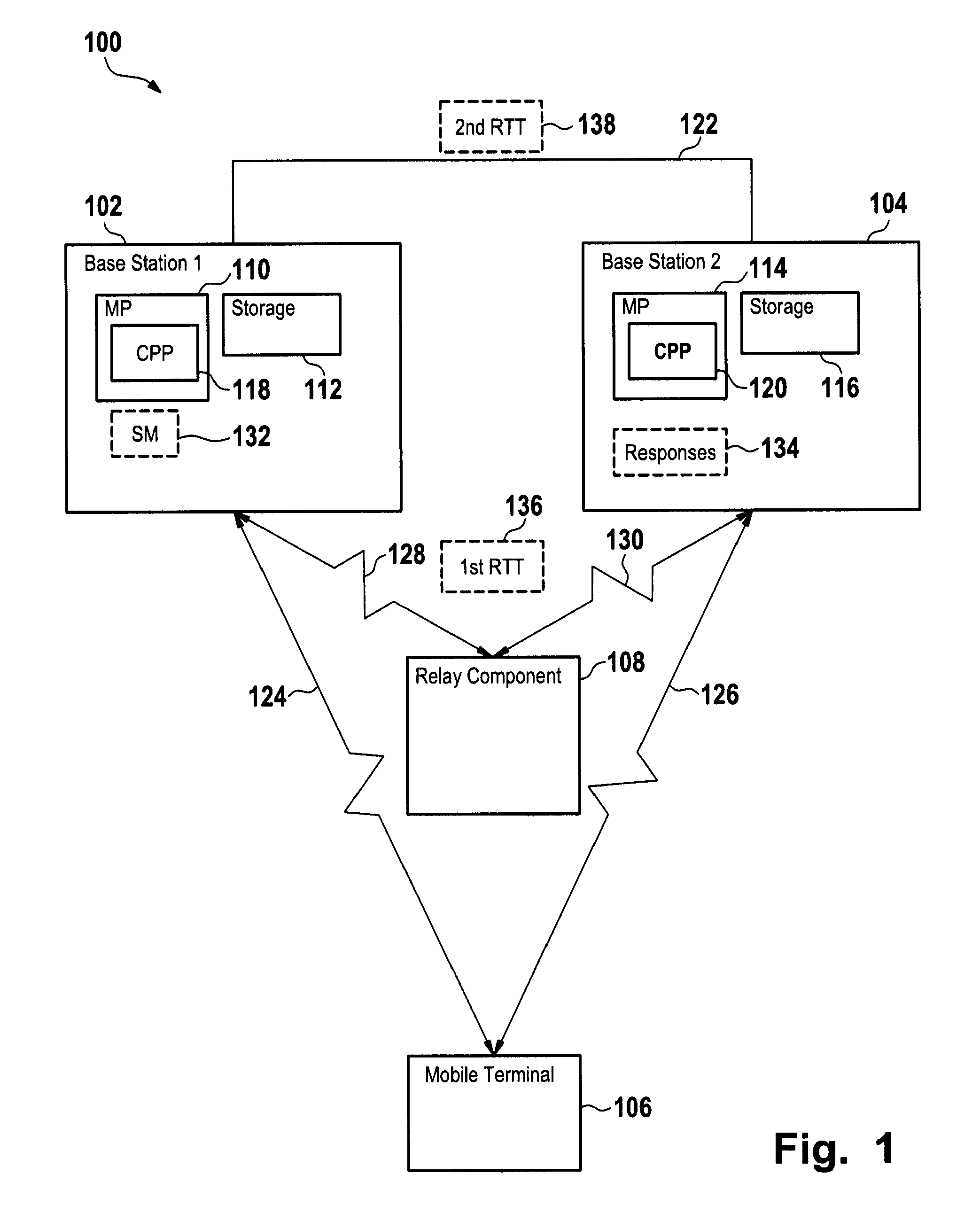
[0006]Instead of sending the signaling messages from the first base station over the network's fixed infrastructure, e.g. over the backhaul network, to the second base station, the signaling messages are sent via a radio link of the communication network to a relay component from where they are further transmitted to the second base station. This provides the advantage that the signaling messages arrive quicker at the second base station than via the network's fixed infrastructure, especially when the second base station is far apart from the first base station with respect to the network's topology.
[0007]In accordance with an embodiment of the invention, the first base station receives responses to the signaling messages from the second base station via the relay component. A response might be a further signaling message sent in response to the reception of a signaling message from the second base station via the relay component to the first base station or might be an acknowledge message. Thus, signaling messages are exchanged between the two base stations over the relay component. Hence, the round trip time of a signaling message might be much lower than the round trip time of a signaling message which is sent over the fixed network's infrastructure. This allows better synchronization of physical layer signals, scheduling mechanisms and datagram transmission. The service with respect to which the signaling messages are exchanged can then be provided with less delay and higher throughput and / or reliability to the terminal by both base stations. Hence, time critical applications running on the terminal and which make use of the service are improved.
[0010]In accordance with an embodiment of the invention, the signaling messages sent by the first base station to the second base station are cryptographically secured. Further, the responses received by the first base station from the second base station are cryptographically secured, either by encrypting the entire signaling messages and responses or by attaching a cryptographic signature to them. This provides the advantage that the relay component over which the signaling messages and the responses are sent is not able to manipulate the signaling messages. The first base station might for example employ encryption means to encrypt the signaling messages before transmission, while the second base station employs decryption means to decrypt the encrypted signaling messages. Similarly the second base station employs encryption means to encrypt the responses, whereas the first base station employs decryption means to decipher the responses.
[0011]In accordance with an embodiment of the invention, the first and second base stations provide the service to the terminal while the terminal is handed over according to a soft handover from the first base station to the second base station. As has been elucidated in the background section, two base station serve simultaneously a terminal during a soft handover. The method in accordance with the invention is particularly advantageous when performed during a soft handover as the delay on services to be delivered to the terminal during the handover can be reduced, maybe even drastically.

Problems solved by technology

A long round trip time for the exchange of signaling messages might lead to delays in the simultaneous delivery of the datagrams to the mobile terminal and might therefore negatively affect time critical applications running on the mobile terminal that make use of the datagrams.

Method used


Image

  • Method of transmitting signaling messages
  • Method of transmitting signaling messages
  • Method of transmitting signaling messages

Examples


Embodiment Construction

[0026]FIG. 1 shows schematically a block diagram of a communication network 100. The communication network 100 comprises a first base station 102 and a second base station 104. The first base station 102 comprises a microprocessor 110, and a storage 112. Similarly, the second base station 104 comprises a microprocessor 114, and a storage 116. The microprocessor 110 executes a computer program product 118 which is for example permanently stored on the storage 112 and loaded for execution into the microprocessor 110. Similarly, the microprocessor 114 of the second base station 104 executes a computer program product 120 which is permanently stored on the storage 116 and loaded for execution into the microprocessor 114.

[0027]The first base station 102 is connected via a wired communication path 122, e.g. a communication path provided by the backhaul network, with the second base station 104. Further, the first base station 102 holds an active connection over communication link 124 with...


PUM


Abstract

There is provided a method of transmitting signaling messages. In accordance with an embodiment of the invention, the method is performed by a first base station of a communication network. The first base station and the second base station of the communication network provide simultaneously a service to a terminal. The first base station transmits signaling messages relating to the provision of the service to the second base station via a relay component. The relay component is linked with the first base station and the second base station via radio links of the communication network. The relay component may be comprised in the terminal to which the service is provided or another terminal with corresponding functionality or a dedicated relay component of the communication network.

Description

[0001]The invention is based on a priority application EP 07 290 774.4 which is hereby incorporated by reference.TECHNICAL FIELD[0002]The invention relates to a method of transmitting signaling messages in a communication network between base stations in general and to a method of transmitting signaling messages between base stations via radio links in particular.BACKGROUND OF THE INVENTION[0003]A terminal located in a cell of a cellular communication network is usually served by the base station of the communication network which provides radio coverage for this cell. There are however scenarios when a terminal is served by more than one base station. For example, the terminal being located in a cell of the network and served by a first base station might be handed over in a so called soft handover to a second base station which provides radio coverage to the neighboring cell. During the soft handover, the terminal is served by the first and by the second base station simultaneousl...

Claims


Application Information

Patent Timeline
IPC IPC(8): H04W4/00H04W36/08H04W76/00H04W88/04H04W92/20
CPCH04W36/08H04W92/20H04W88/04H04W76/00
Inventor TABERY, PETERSCHAEPPERLE, JOERG
Owner WSOU INVESTMENTS LLC
Learn More