In Tyre Sound Absorber

a technology of sound absorber and tyre, which is applied in the direction of non-skid devices, weaving, transportation and packaging, etc., can solve the problems of insufficient strength of noise absorber and damage of noise absorber, and achieve the effect of increasing air flow resistan

Active Publication Date: 2010-01-07
ZEPHYROS INC
View PDF20 Cites 9 Cited by
  • Summary
  • Abstract
  • Description
  • Claims
  • Application Information

AI Technical Summary

Benefits of technology

[0009]The low air flow resistance of the first layer allows the standing sound pressure wave to propagate within the layer where the particle velocity of the radial pressure wave that creates the tonal noise is in a normal direction to the direction of the pressure wave. The excited air particles are thereby forced through the high air flow resistance of the second layer to provide the sound absorption.
[0010]Preferably the first and second layers are made from non-woven fibrous webs. In a preferred embodiment, the first fibrous layer has fibers orientated substantially perpendicular to the surface of the wheel rim. The orientation substantially perpendicular to the surface of the wheel rim provides an increased tensile strength of the sound absorber in the direction perpendicular to the surface of the wheel rim when contrasted with conventional bulky non-woven fabrics in which the fibers are cross-lapped. This is particularly advantageous for embodiments where the centrifugal forces increase with the rotational speed of the wheel during operation and the increased tensile strength in the direction perpendicular to the surface of the wheel rim decreases the risk of delamination of the sound absorber.
[0011]Preferably, the air flow resistance of the respective layers is substantially consistent to provide a relatively constant acoustic absorption to reduce the tonal noise. In some embodiments, the ratio of air flow resistance of the second layer to the first layer is between 25:1 and 35:1. That is the air flow resistance of the second layer is between 25 and 35 times that of the first layer. In some embodiments, the ratio is approximately 30:1.
[0015]According to another aspect of the present invention, a tire sound absorbing system includes a tire, a wheel rim, the wheel rim and tire forming an enclosed tire cavity, and a porous insert disposed adjacent a surface of the wheel rim within the tire cavity, the porous insert comprising an inner fibrous layer proximal to the wheel rim surface and an outer fibrous layer distal to the wheel rim surface, the outer fibrous layer has a higher air flow resistance than the inner fibrous layer, and wherein the porous insert is shaped to avoid damage during fitment of the tire on the rim.
[0016]The porous insert is shaped so that the bead of the tire is able to push aside the sound absorber during fitment so that damage to the sound absorber is avoided. The porous insert has rounded edges to assist the tire bead in pushing the sound absorber to a position where the risk of damage is reduced. Even more preferably the rounded edges are formed by thermoforming. The rounded edges can be slit or notched to avoid creasing of the porous insert.

Problems solved by technology

However, it is often a problem with the prior art that the noise damper can be damaged during fitment of the tire on the wheel rim or the noise damper is not physically strong enough to resist tearing or breaking apart during normal operation.

Method used


Image

  • In Tyre Sound Absorber
  • In Tyre Sound Absorber
  • In Tyre Sound Absorber

Examples


example 1

[0042]A prototype tire sound absorber, according to one embodiment of this invention with a lower air flow resistance spacer layer and a higher air flow resistance thermoformable acoustic sheet, was made up and attached to alloy wheel rims using a pressure sensitive adhesive. Low profile tires were then fitted to the rim in the normal manner.

[0043]The alloy wheel rims were 18 inches diameter by 8 inches wide and the tires were Pontenza RE55S, 265 / 35ZR18.

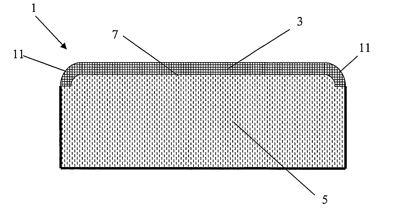
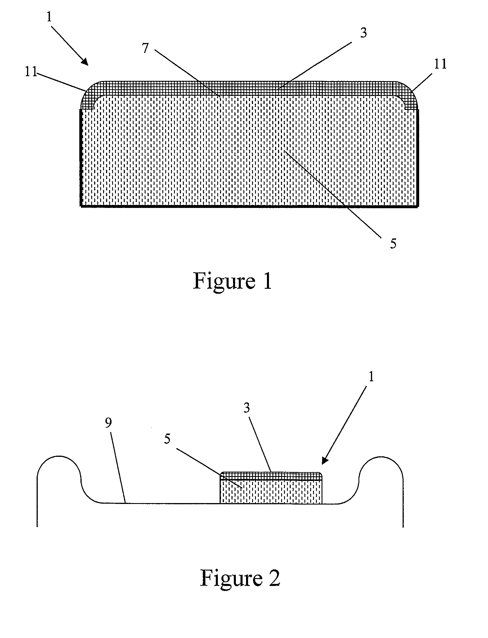
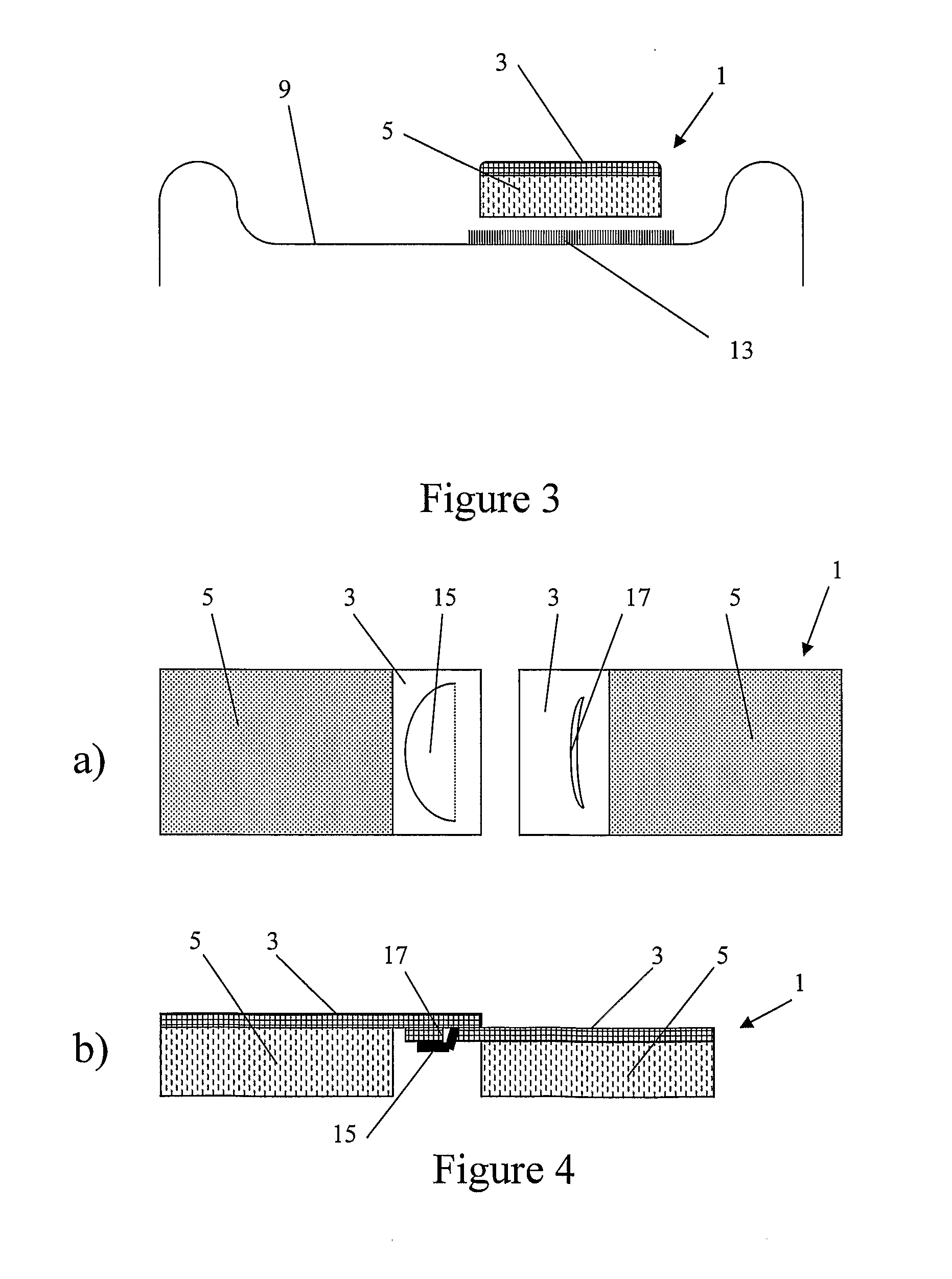
[0044]The sound absorber measured 20mm thick, 90mm wide and molded with a radius on the leading edge.

[0045]The sound absorber had a thermoformable acoustic sheet with a measured spatial average flow resistance of 600 Rayls, and weighed 180 g / m2, with a thickness of approximately 0.5 mm.

[0046]The spacer layer had a density of 600 g / m2, and consisted of a blend of polyester fibers with an average fiber size of 6-denier. The spacer consisted of 30% polyester bicomponent fiber and 70% polyester staple fiber. The spatial average air flow ...


PUM

PropertyMeasurementUnit
air flow resistanceaaaaaaaaaa

Abstract

An in tire sound absorber for a pneumatic wheel assembly including a wheel rim and a tire fitted to the wheel rim. The sound absorber comprises a first fibrous layer and a second fibrous layer with a higher air flow resistance than the first layer. The sound absorber is configured to fit around the wheel rim with the first layer in contact with a surface of the wheel rim and extending substantially between the second layer and the wheel rim.

Description

BACKGROUND[0001]1. Technical Field[0002]This invention relates to an in-tire sound absorber for the reduction of tonal sounds in pneumatic tires.[0003]2. Description of the Related Art[0004]Tonal sound is caused by a standing wave generated in the space between the tire and wheel rim. This standing wave relates to the geometry of the tire, and the temperature and pressure of the air in the tire cavity. The resultant tone or sound is typically below 600 Hz.[0005]The problem of tonal noise transmission into the motor vehicle cabins has been addressed by a number of means. U.S. Pat. No. 6,755,483 (Sumitomo Rubber Industries, Ltd.) describes the use of a noise damper disposed in the cavity formed between the rim and the tire. The noise damper is made from porous material which has a specific density of between 0.005 and 0.06 and in particular an open-cell polyurethane foam. In one embodiment, the noise damper has an uneven facing, or is made from an outer layer having low sound reflecti...

Claims


Application Information

Patent Timeline
Patent Type & Authority Applications(United States)
IPC IPC(8): B60C19/00B32B5/26
CPCB60C19/002B60B21/12Y10T442/659B60C19/00B60B2360/322B60B2900/133B60C5/00
Inventor KIERZKOWSKI, MAREK HENRYKGIBBONS, PHILIP JOHNGASCOIGNE, BRUCE REGINALDCOATES, MICHAEL WILLIAM
Owner ZEPHYROS INC
Why Eureka
Try Eureka