Apparatus for continuous strip casting

a technology of continuous strip and casting apparatus, which is applied in the direction of casting apparatus, manufacturing tools, mould control devices, etc., can solve the problems affecting the surface quality of cast strips, and achieve the effect of increasing oxidation and scale formation, and influencing the surface quality

Inactive Publication Date: 2010-01-07
NUCOR CORP
View PDF6 Cites 15 Cited by
  • Summary
  • Abstract
  • Description
  • Claims
  • Application Information

AI Technical Summary

Benefits of technology

[0005]The conditions provided for the just cast strip in the first enclosure influences the quality of the cast strip. We have found that microcracks in the surface of the finish cast strip can be traced to strain in the strip in the first enclosure as it moves through the loop and across the roller table into the first pinch rolls. Additionally, we have

Problems solved by technology

Additionally, we have found that the oxygen and water vapor levels of the atmosphere in the first enclosure i

Method used


Image

  • Apparatus for continuous strip casting
  • Apparatus for continuous strip casting
  • Apparatus for continuous strip casting

Examples


Embodiment Construction

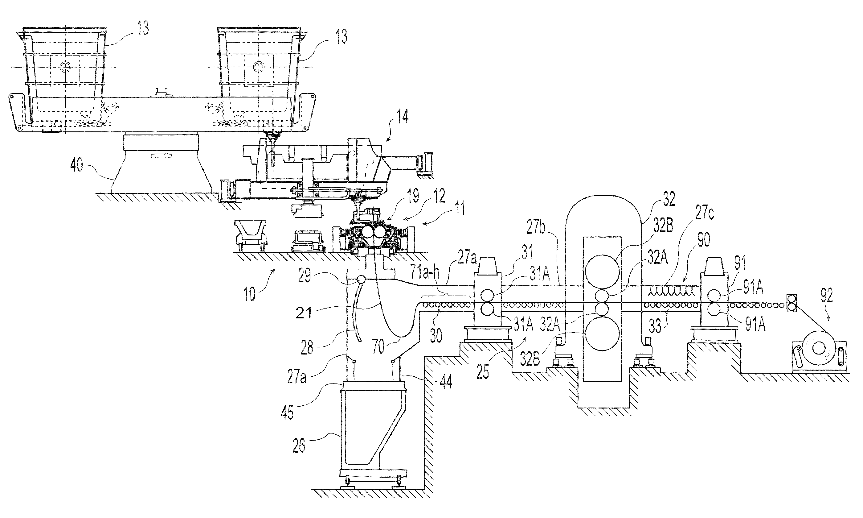
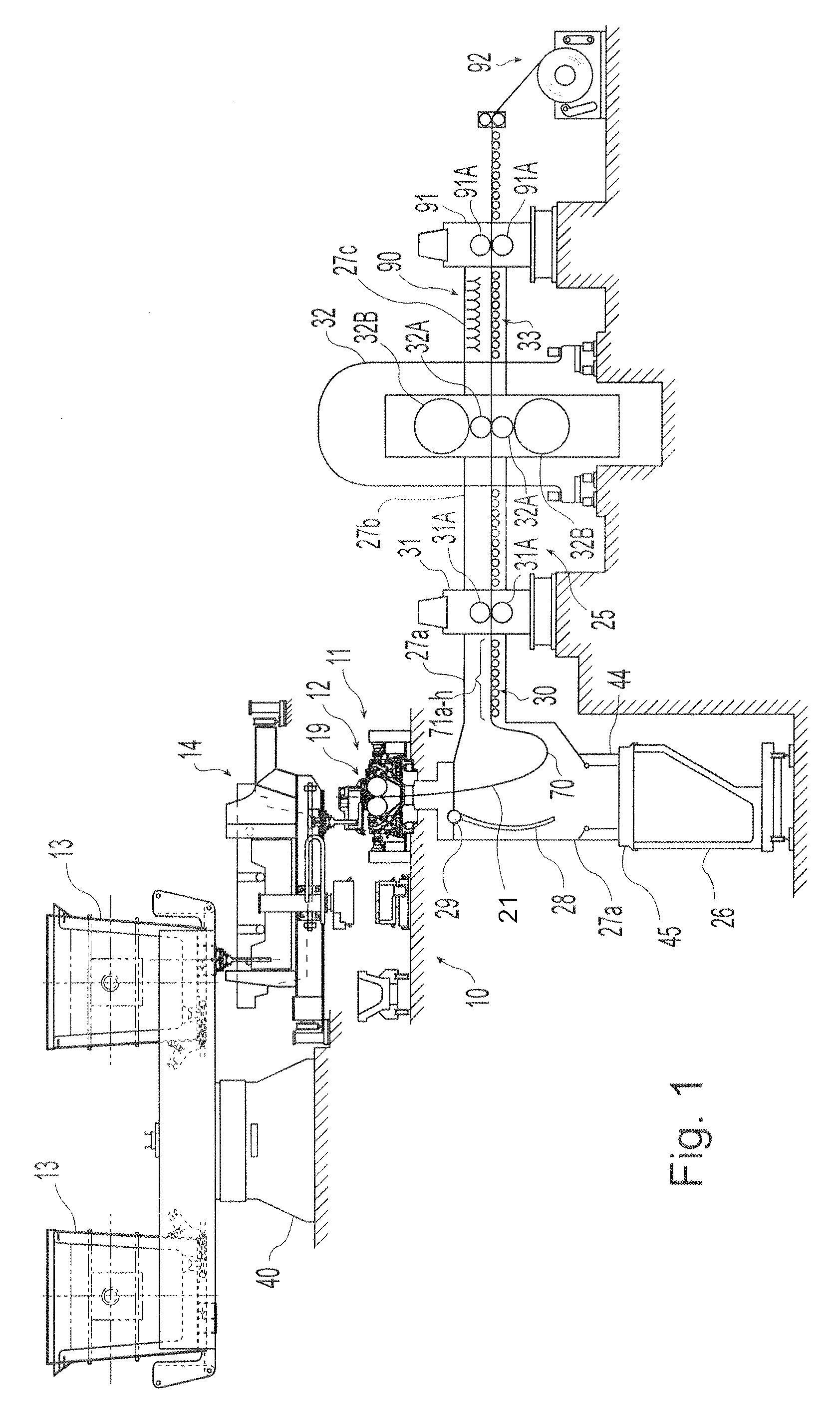
[0031]Referring now to the drawings, there is illustrated in FIGS. 1 through 4, a twin roll caster is illustrated that comprises a main machine frame 10 and supports a pair of counter-rotatable casting rolls 12 mounted in a module in a roll cassette 11. The casting rolls 12 have casting surfaces laterally positioned to form a nip there between.

[0032]Molten metal is supplied from a ladle 13 through a metal delivery system 14 to a metal delivery nozzle, or core nozzle, positioned between the casting rolls 12 above the nip. The delivered molten metal is delivered to form a casting pool 19 of molten metal above the nip supported on the casting surfaces of the casting rolls 12. This casting pool 19 is confined in the casting area at the ends of the casting rolls 12 by a pair of side closures or side dams. The upper surface of the casting pool 19 (generally referred to as the “meniscus” level) may rise above the lower end of the delivery nozzle so that the lower end of the delivery nozzle...


PUM

PropertyMeasurementUnit
Lengthaaaaaaaaaa
Lengthaaaaaaaaaa
Lengthaaaaaaaaaa

Abstract

An apparatus for continuously casting thin strip includes a caster having a pair of casting rolls having a nip there between capable of delivering cast strip downwardly from the nip and an first enclosure capable of forming a protective atmosphere into which the strip can be formed in loop to extend over a plurality of rollers into pinch rolls with the strip having a strain of less than 0.4%, which may be provided by a plurality of rollers at entry of the strip into the pinch rolls to carry the strip into the pinch rolls, with at least a first entry roller having a diameter between 200 and 650 millimeters and being below a majority of other rollers.

Description

BACKGROUND AND SUMMARY[0001]This invention relates in general to the casting of metal strip by continuous casting in a twin roll caster.[0002]In a twin roll caster, molten metal is introduced between a pair of counter-rotated laterally positioned casting rolls that are internally cooled so that metal shells solidify on the moving casting surfaces and are brought together at a nip between the rolls to form a solidified strip product, delivered downwardly from the nip between the rolls. The term “nip” is used herein to refer to the general region at which the casting rolls are closest together. The molten metal may be poured from a ladle into a smaller vessel or series of smaller vessels from which it flows through a metal delivery nozzle located above the nip, forming a casting pool of molten metal supported on the casting surfaces of the rolls immediately above the nip and extending along the length of the nip. This casting pool is usually confined between side plates or dams held i...

Claims


Application Information

Patent Timeline
IPC IPC(8): B22D11/06B22D2/00B22D46/00
CPCB21B1/463B22D11/14B22D11/1206B22D11/0622
Inventor DIXON, ANDREW EDWARDMCQUILLIS, GARYMAHAPATRA, RAMA BALLAVWOLLEY, LEIGH
Owner NUCOR CORP
Why Eureka
Try Eureka