Heating and heat recovery unit for an air conditioning system

a technology of heat recovery unit and air conditioning system, which is applied in the direction of indirect heat exchangers, lighting and heating apparatus, heating types, etc., can solve the problems of difficult to maintain water temperature, large water tank heat loss, and relatively long time requirements, so as to improve heating and heat recovery, improve heat recovery efficiency, and increase the temperature of water outflow.

Inactive Publication Date: 2010-01-07
CHANG TSUNG CHE
View PDF5 Cites 37 Cited by
  • Summary
  • Abstract
  • Description
  • Claims
  • Application Information

AI Technical Summary

Benefits of technology

[0006]The primary objective of the present invention is to provide an improved heating and heat recovery unit for supplying hot water, which is primarily structured to comprise more than one different sized insulated water storage tanks internally installed in the unit of the present invention. Each of the tanks can be independently heated to raise the temperature thereof. The heat exchange flow process consists of heating of cold water after input at a cold water inlet end, and heating the water before output at a hot water outlet end, thereby substantially increasing the water outflow temperature, speed of heat exchange at the water outlet end and heat recovery efficiency. Hence, apart from saving electric power, moreover, enables retarding thereby retarding the speed at which the temperature of the system drops due to the low cold water temperature in winter.

Problems solved by technology

Heating of such a huge water tank is extremely slow; moreover, it is difficult to maintain the water temperature.
During winter, a relatively long time is required before being able to supply hot water, which not only consumes electric power, moreover, the temperature that the hot water is maintained at is often insufficient.

Method used


Image

  • Heating and heat recovery unit for an air conditioning system
  • Heating and heat recovery unit for an air conditioning system

Examples


Embodiment Construction

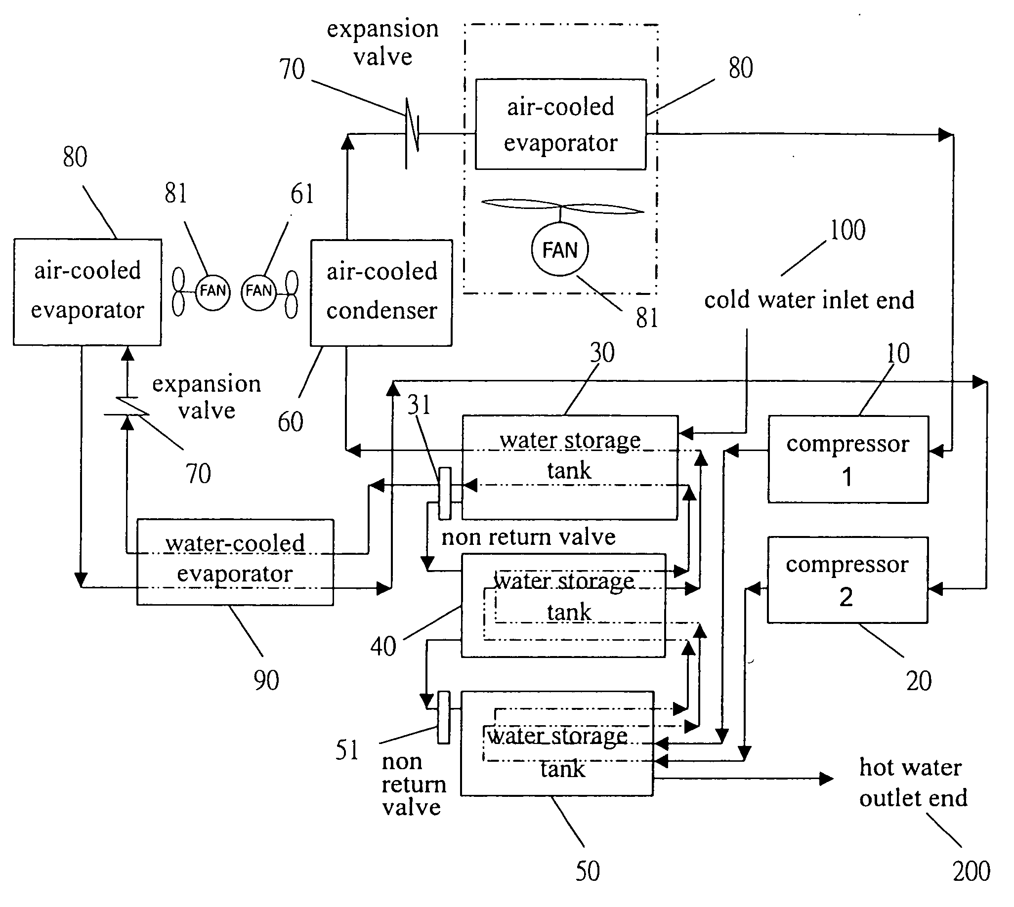
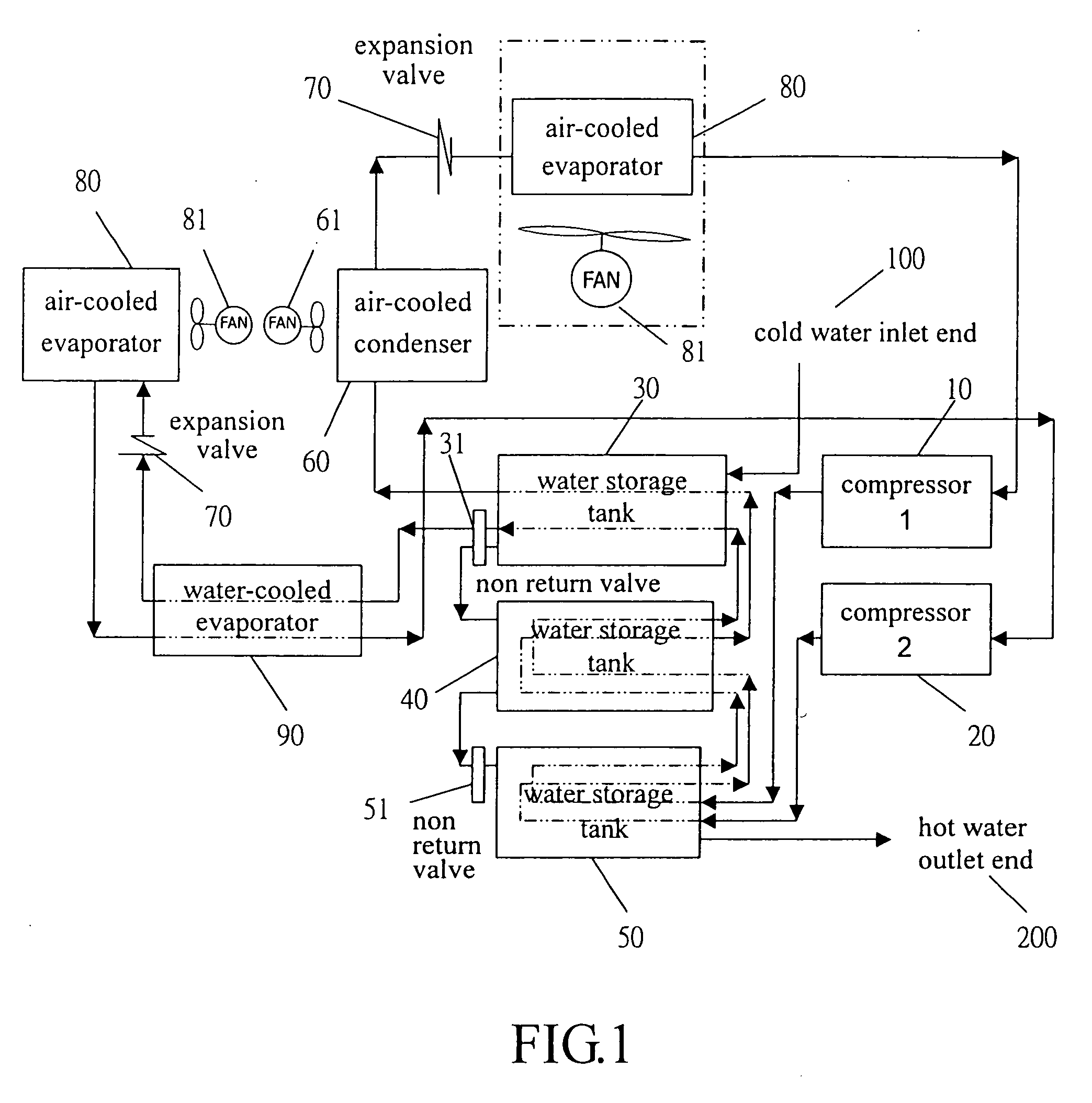
[0009]Referring to FIG. 1, the present invention is structured to comprise first and second compressors 10, 20, large, medium and small insulated water storage tanks 30, 40, 50, an air-cooled condenser 60, an expansion valve 70, air-cooled evaporators 80 and a water-cooled evaporator 90, wherein the first compressor 10 is suitable for various types of air conditioner heat recovery systems, and the second compressor 20 is suitable for refrigerant heat pump water heater systems. Working method of a refrigerant of the present system involves using a high-temperature and high-pressure end refrigerant of the first, second compressors 10, 20 to pass through bottom end heat exchangers (plate type, fin type, bare pipe) within the small, medium and large insulated water storage tanks 50, 40, 30 to effect heat exchange with water, and the heat is stored within the small, medium and large insulated water storage tanks 50, 40, 30. When the temperature reaches a set value, then surplus heat is d...


PUM


Abstract

A heating and heat recovery unit for an air conditioning system, which is assembled from compressors, several insulated water storage tanks, an air-cooled condenser, expansion valves, air-cooled evaporators and a water-cooled evaporator. The compressors are suitable for various types of air conditioning systems and refrigerant heat pump water heater systems. The installed water storage tanks are arranged according to size, from the largest at the top down to the smallest at the bottom. A high-temperature and high-pressure refrigerant from the compressors is first input into the smallest tank, and after passing through to the largest tank, it is then passed on to the expansion valve and the evaporator. A configuration of cold water pipes is provided for input into the largest tank through to the smallest tank 50, and output therefrom. Hence, the heat exchange flow process consists of heating of cold water after entering from a cold water inlet end, and heating the water before output at a hot water outlet end, moreover, each of the tanks can be independently heated to raise the temperature thereof.

Description

BACKGROUND OF THE INVENTION[0001](a) Field of the Invention[0002]The present invention relates to a heating and heat recovery air conditioning system, which is able to substantially increase the water outflow temperature, speed of heat exchange at the water outlet end and heat recovery efficiency, thereby retarding the speed at which the temperature of the system drops due to the low cold water temperature in winter.[0003](b) Description of the Prior Art[0004]Conventional type water heaters that supply hot water use an evaporator to absorb ambient transmitted heat and change it into a gaseous refrigerant. After the gaseous refrigerant is compressed using a compressor, then it is converted into a high-temperature and high-pressure vapor, which is circulated in a condenser to heat water within the water heater.[0005]The aforementioned water heaters are provided with a water tank of considerably large capacity, and after cold water is input into the water tank through a cold water inle...

Claims


Application Information

Patent Timeline
Patent Type & Authority Applications(United States)
IPC IPC(8): F25B29/00
CPCF24D11/0214F25B29/003F25B2339/047F25B2400/06Y02E60/142F28D2020/0078F28D2020/0082Y02B30/126F28D20/0034Y02E60/14
Inventor CHANG, TSUNG-CHE
Owner CHANG TSUNG CHE
Why Eureka
Try Eureka